


Model 117A4 Carrier Installation Instructions Installing Multiple Carriers
Model 117A4 Carrier Installation Instructions
503-801-18026 Issue 2 February 1999
6
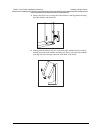
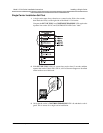
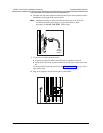
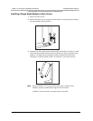
Insert the free end of the expansion cable into the IN jack of the expansion carrier
immediately to the right of the control carrier.
Note:
Although installing an expansion cable into the wrong IN or OUT jack
will not harm either carrier, doing so causes all handsets to work
improperly and the OUT OF SYNC LED to light.
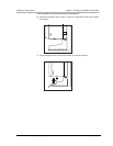
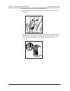
7
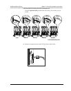
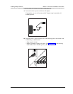
If you have a second expansion carrier:
a
Connect an expansion cable to the OUT jack of expansion carrier #1.
b
Insert the free end of the expansion cable into the IN jack of expansion carrier
#2.
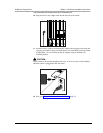
If you have a third expansion carrier, see the cabling illustration on page 34 for a
four-carrier setup.
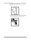
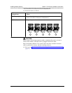
8
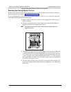
Plug an AC adapter cord into the left side of each carrier.
CAUTION
USE ONLY
AT&T CABLE
P⁄N 847667896
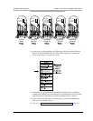
IN
OUT
From
Control
Carrier
OUT OF SYNC
CONTROL/
EXPANSION
1 2345