


Model 117A4 Carrier Installation Instructions Understanding Carriers
Model 117A4 Carrier Installation Instructions
503-801-1804 Issue 2 February 1999
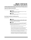
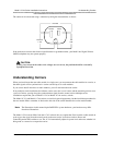
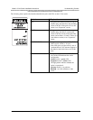
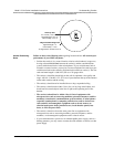
The outlet can also be tested using a voltmeter by taking the measurements as shown:
If the outlet does not meet the electrical specifications for grounded outlets, your Multi-Line Digital Wireless
(MDW) telephone may not operate properly.
Understanding Carriers
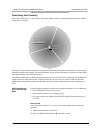
When you install more than one radio module in a single zone, you must mount the radio modules in a carrier, so
that their signals will be synchronized. A carrier can hold up to six radio modules.
If you want to install more than six radio modules, you will need more than one carrier.
If any multiple-carrier installation, the leftmost carrier acts as the control carrier, and the remaining carriers act as
expansion carriers, passing along the synchronization signal from the control carrier. Multiple carrier
installations require that you use Model 117A3 or Model 117A4 carriers, or both.
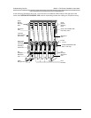
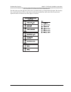
The Model 117A3 and Model 117A4 carriers are similar in general appearance, but the installation procedure for
the two models differs somewhat. A label on the left side of the carrier identifies the carrier model number.
The Model 117A4 carrier differs from the 117A3 in that it does not require that Slot 6 contain a radio module in
order to pass the signal from the control carrier to the next carrier. It also does not have Power and
Control/Expansion DIP switches to set. The 117A4 automatically adjusts its power level and senses whether it is
being used as a control or an expansion carrier.
!
CAUTION:
If there is no current to the outlet or the voltages are not correct, the problem should be corrected by
a qualified electrician.
Note:
The illustrations in this manual depict PARTNER
®
system hardware; your hardware may differ
from these illustrations.
120 Volts
Neutral
Less than
1 volt
120
volts
G
Phase