


Model 117A4 Carrier Installation Instructions Understanding Carriers
Model 117A4 Carrier Installation Instructions
503-801-1806 Issue 2 February 1999
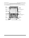
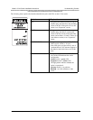
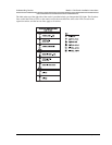
The following chart explains the label that identifies the jacks and LEDs on the 117A4 carrier.
Label Explanation
IN Designates the modular jack that accepts the
modular plug and cable from the preceding
carrier to the left. If the jack is in use, this
carrier is an “Expansion” carrier.
OUT Designates the modular jack that accepts a
modular plug and cable to connect this
carrier to the next carrier to the right. This
carrier can be either a “Control” carrier (if it
is the leftmost carrier) or an “Expansion”
carrier.
OUT OF SYNC Designates the upper of two LEDs. If the
LED is not lit, carrier is “in sync.”
If the LED glows red, the carrier is out of
synchronization. Call Customer Support as
described on the inside front cover of this
book.
CONTROL/EXPANSION Designates the lower of two LEDs. The
color of the LED indicates the carrier
configuration:
Control carrier = green LED
Expansion carrier = amber LED
The light pattern indicates whether the
carrier is operational:
Glowing steadily = no problem.
Blinking = no radio module(s) in the
carrier.