


Model 117A4 Carrier Installation Instructions Understanding Carriers
Model 117A4 Carrier Installation Instructions
503-801-18010 Issue 2 February 1999
General Positioning
Rules
Failure to observe the following rules regarding location and use will result in poor
performance of your MDW telephone.
•
Position the carrier(s) in a central location, relative to the handset(s) usage area,
leaving at least 6 feet (1.8 m) between the carrier(s) and the communications
system switch/control unit or other wired phones. If your switch/control unit is
located in a remote location, you may have to run a telephone line cord from your
switch/control unit to the centrally positioned radio module or carrier(s). The line
cord maximum length is 1,000 feet (305 m) of 26-gauge cable.
•
The carrier(s) should be placed high on the wall for optimum voice quality and
range. Allow 6–12 inches (15.2–30.5 cm) of space between the top of the antenna
on the radio modules and the ceiling.
•
The carrier(s) should never be installed above a drop, suspended ceiling.
•
The carrier(s) should not be within 3 feet (.9 m) of any large metal object, and
should not have metal objects in the line of sight to the operating area of the
handset.
•
The carrier(s) should not be within 6 feet (1.8 m) of equipment with
microprocessors such as answering machines, personal computers, and fax
machines; control units, communications system switches, or other phones
(especially speakerphones); competing radio devices such as wireless bar-
code scanners; electromagnetic equipment such as electric motors; or
electrical main power feeds, junction boxes, circuit-breaker panels, fuse
boxes, or 220-volt power lines.
•
The carrier(s) should not share the same power line as equipment with
microprocessors such as answering machines, personal computers, and fax
machines; or electromagnetic equipment such as electric motors.
•
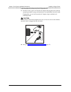
If your communications system uses an uninterruptible power supply, such as a
backup generator, you may want to connect the radio module or carrier(s) to that
power supply.
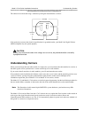
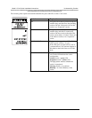
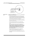
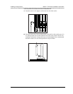
POWER
RADIO
PASS
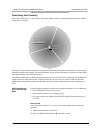
Radio
Module
5 to 10 feet (1.5 to 3.1 m)
Signal Strength = 9 to 10
Voice Quality = 9 to 10
Close-Up Test
Signal Strength = 3
Voice Quality = 7 to 8
*At High Power—Power Level = 8
*Edge-of-Usable-Range Test