


Model 117A4 Carrier Installation Instructions Understanding Carriers
Model 117A4 Carrier Installation Instructions
503-801-1808 Issue 2 February 1999
Positioning Your Carrier(s)
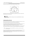
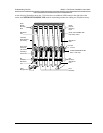
Each carrier holds up to six radio modules. Each radio module and its corresponding handset operates within a
single zone of coverage.
The range of your handset(s) depends on your particular operating environment. For indoor use, walls between
the handset and the radio module will reduce the phone’s range. Avoid concentrations of structural metal, such as
steel and aluminum, and reinforced concrete.
The MDW telephones have a built-in testing feature that you can use before final installation to help determine
proper placement of the radio module. To perform the tests, all you need is an electrical outlet for the radio
module and a charged battery pack in the handset (you do not need a communications system switch/control
unit).
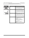
Performance/Range
Test in Wireless Test
Mode
Using the signal-strength test and the voice-quality test together, you can determine:
•
if the installation has been done correctly.
•
if the handsets and bases are working properly.
•
the range in which your MDW 9031/9031DCP Pocket Phone performs best at
your site.
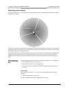
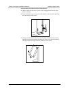
Close Up Test
At no more than 5–10 feet (1.5–3.1 m) from its radio module, use the following
procedure:
1
Make sure the handset is turned off.
2
Press and hold the Select button (" ) for three seconds.
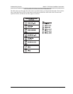
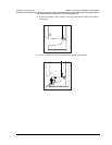
Single Radio Module,
Single Carrier, or
Multiple Carriers
POWER
RADIO
PASS
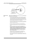
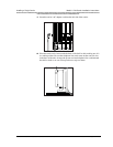
Single Radio Module,
Single Carrier, or
Multiple Carriers
Approximately
500 to 900 feet in a
typical office building;
up to 1200 feet in
an unobstructed
environment
Approximately
500 to 900 feet in a
typical office building;
up to 1200 feet in
an unobstructed
environment