


Model 117A4 Carrier Installation Instructions Installing Multiple Carriers
Model 117A4 Carrier Installation Instructions
503-801-18024 Issue 2 February 1999
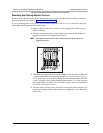
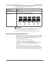
Mounting and Cabling Multiple Carriers
Be sure you have determined the optimal placement for your carrier using the Performance/Range test and the
positioning guidelines described in “Positioning Your Carrier(s).”
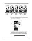
If you are installing with 117A3 carriers, see your MDW telephone Installation and Use manual for the proper
Power and Control/Expansion DIP switch settings.
1
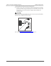
Check to make sure the carrier’s power cord is unplugged from the wall outlet
before continuing.
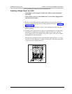
2
Choose a location backed by a wooden stud for the carrier (if unavailable, use
toggle bolts instead of the supplied wood screws).
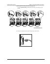
Note:
The leftmost carrier must be the control carrier; all of the others are
expansion carriers.
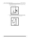
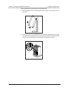
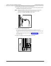
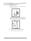
3
Place the carrier against the wall, leaving enough room to the right for additional
carrier(s) if applicable. Hold the carrier straight; use a level if needed. Using a
nail or pencil, mark screw locations through the four wall-mount holes. Start the
screws, leaving the screw heads protruding approximately ½" (12 mm) from the
wall. Repeat Steps 1 through 3 for each carrier, leaving 1 foot (0.3 m) optimally
to 4 feet (1.2 m) between carriers.
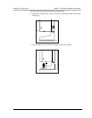
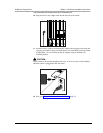
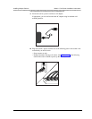
4
Place the carrier over the screws, then slide it downward to lock it into place. Be
sure that the leftmost carrier is the control carrier. Tighten the screws. Repeat for
each carrier.
1 2 3 4
6
T
RANS
T
ALK
5
CAUTION
U
SE
O
N
L
Y
A
T&
T C
A
B
LE
P⁄N
8
476
67
8
96
IN
O
U
T
OUT O
F S
YN
C
C
ONT
R
OL
/
EX
P
A
NSIO
N
MNNOEA
PTRH
AN
HAPTERG
R
REPR
ACITE-O
K
LO
REM
IPSUM
REPR
ACITE-OK
REPRACITE-O
K
XERTFAM
R
U
KLARIEN
LO
REPRAC
ITE-OK
LO
R
EM
IPSUM
XERTFAM
RU
KLA
RIENLO