


Understanding Carriers Model 117A4 Carrier Installation Instructions
Model 117A4 Carrier Installation Instructions
503-801-180
Issue 2 February 1999 5
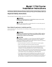
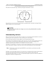
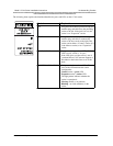
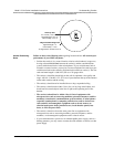
As the following illustration shows, the 117A4 does have an additional LED located on the right side of the
carrier, the CONTROL/EXPANSION LED, used for determining whether the cabling was installed correctly.
1 2 3 4
6
T
RANS
T
ALK
5
MNNOEAPTRHAN
HAPTERGR
REPRACITE-OK
LOREMIPSUM
REPRACITE-OK
REPRACITE-OK
XERTFAMRU
KLARIENLO
REPRACITE-OK
LOREMIPSUM
XERTFAMRU
KLARIENLO
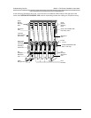
Rear
Exit Slots
Wall Mount
Hole
Slot
Numbers
SYNC and CONTROL/EXP
LED Codes Label
CONTROL/EXPANSION LED
(Model 117A4 Only)
OUT Jack
IN Jack
Cable
Manager Slot
Wall Mount
Hole
Slot
Numbers
Card Edge
Connectors
Power Cord
Connector
(not shown)
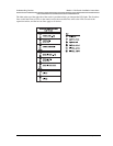
Wall Mount
Hole
Radio
Module
Mounting
Rods
Radio
Module
Mounting
Rods
Label with
Model Number
(not shown)
Wall Mount
Hole
CAUTION
USE ONLY
AT&T CABLE
P⁄ N 847667896
IN
OUT
OUT OF SYNC
CONTROL/
EXPANSION