4
Dancer Communications, Inc.
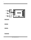
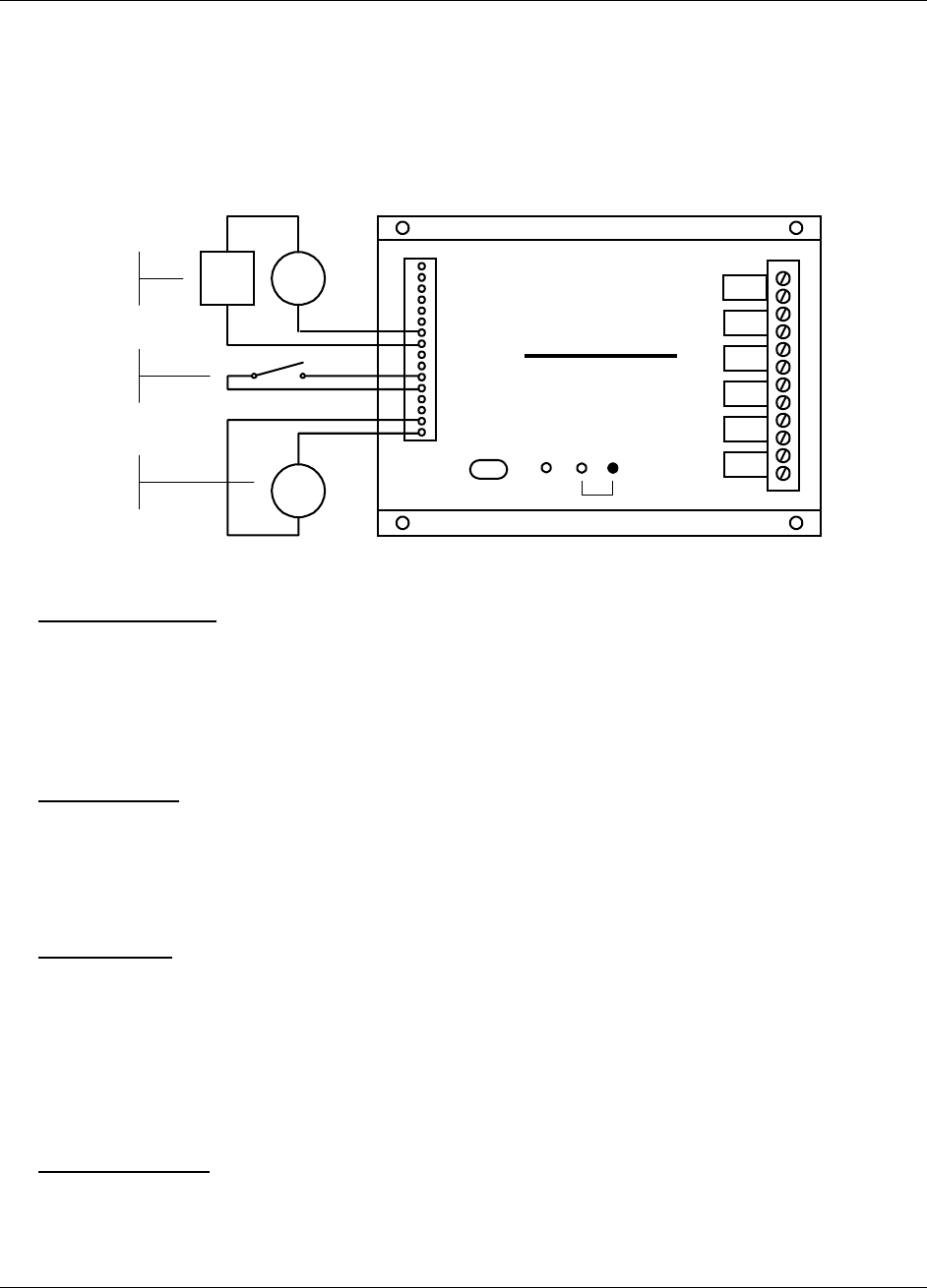
Input Wiring
Inputs should be wired with 14 to 20 gauge wire. Twisted pair cable is recommended for runs in excess of 20
feet. Input devices requiring 12 VDC can be powered from the Messenger 570’s 12 VDC auxiliary output
terminal.
When wiring the inputs, keep in mind that they share a common ground and that the input signals must not
exceed 5 VDC or 25 mA.
Serial Port
Power
Input 1
Common
Model 570
Remote Monitoring System
Alarm
Batt Out
Batt In
Output 4
Output 3
Output 2
Output 1
+12V DC
Common
Input 2
Common
Input 3
Common
Input 4
Common
Input 5
Common
Input 6
Common
Input 7
Common
Input 8
Common
4-20 mA
Sensor
24 VDC
Supply
Temp.
Sensor
-
-
++
4-20 mA
Sensor
Dry
Contact
Temp
Sensor
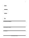
Temperature Sensor
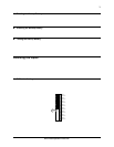
Flip to OFF the shunt resistor DIP switch for the input you want to modify and flip to ON the pull-up resistor
DIP switch.
Attach the temperature sensor to the input screw terminals (contact technical support for a list of compatible
thermistor temperature sensors). Use the INP S command to set the scaling and alarm parameters (refer to the
Command Reference section).
0-5 VDC Sensor
Flip to OFF the shunt resistor DIP switch for the input you want to modify and flip to OFF the pull-up resistor
DIP switch.
Attach the 0-5 VDC sensor to the input screw terminals. Use the INP S command to set the scaling and alarm
parameters (refer to the Command Reference section).
4-20 mA Sensor
Flip to ON the shunt resistor DIP switch for the input you want to modify and flip to OFF the pull-up resistor
DIP switch.
Attach your 4-20 mA sensor to the input screw terminals. Keep in mind that the Messenger 570’s internal shunt
resistor is referenced to common and that no other device in the loop can be referenced to ground. If it is
impossible to isolate the other devices in the loop, you can use a signal isolator or an input expansion module.
Use the INP S command to set the scaling and alarm parameters (refer to the Command Reference section).
Dry Contact Switch
Flip to OFF the shunt resistor DIP switch for the input you want to modify and flip to ON the pull-up resistor
DIP switch.


