3
www.remotepossibilities.com
Enabling the Backup Battery
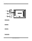
Attach the shorting clip (included with the unit) between the “BATT OUT” and “DC IN” terminals. If the
shorting clip is lost, a short length of wire can be used. Once enabled, the battery will require up to 24 hours to
fully charge.
Disabling the Backup Battery
To disable the backup battery, remove the shorting clip from between the “BATT OUT” and “DC IN”
terminals.
Testing the Backup Battery
When operating from AC power, the power light on the front panel of the Messenger 570 system is green.
When operating from battery, the power light is red.
Test the battery at least once per year by removing the Messenger 570’s AC power source for 10 to 15 minutes
and verifying that the power light changes to red and that the unit responds to an incoming phone call.
Attaching the Inputs
The Messenger 570 system supports eight universal inputs that can accept a variety of input types. Input expansion
modules are available to increase the monitoring capability of the Messenger 570 to 32 inputs (see Input Expansion
Modules).
Inputs 1 through 4 are factory pre-configured to accept 4-20 mA signals while inputs 5 through 8 are factory pre-
configured to accept dry-contact signals. It is easy to re-configure an input to accept 4-20 mA, 0-5 VDC,
thermistor, logic-level, dry-contact or other signal types in any combination.
DIP Switch Settings
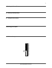
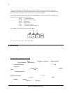
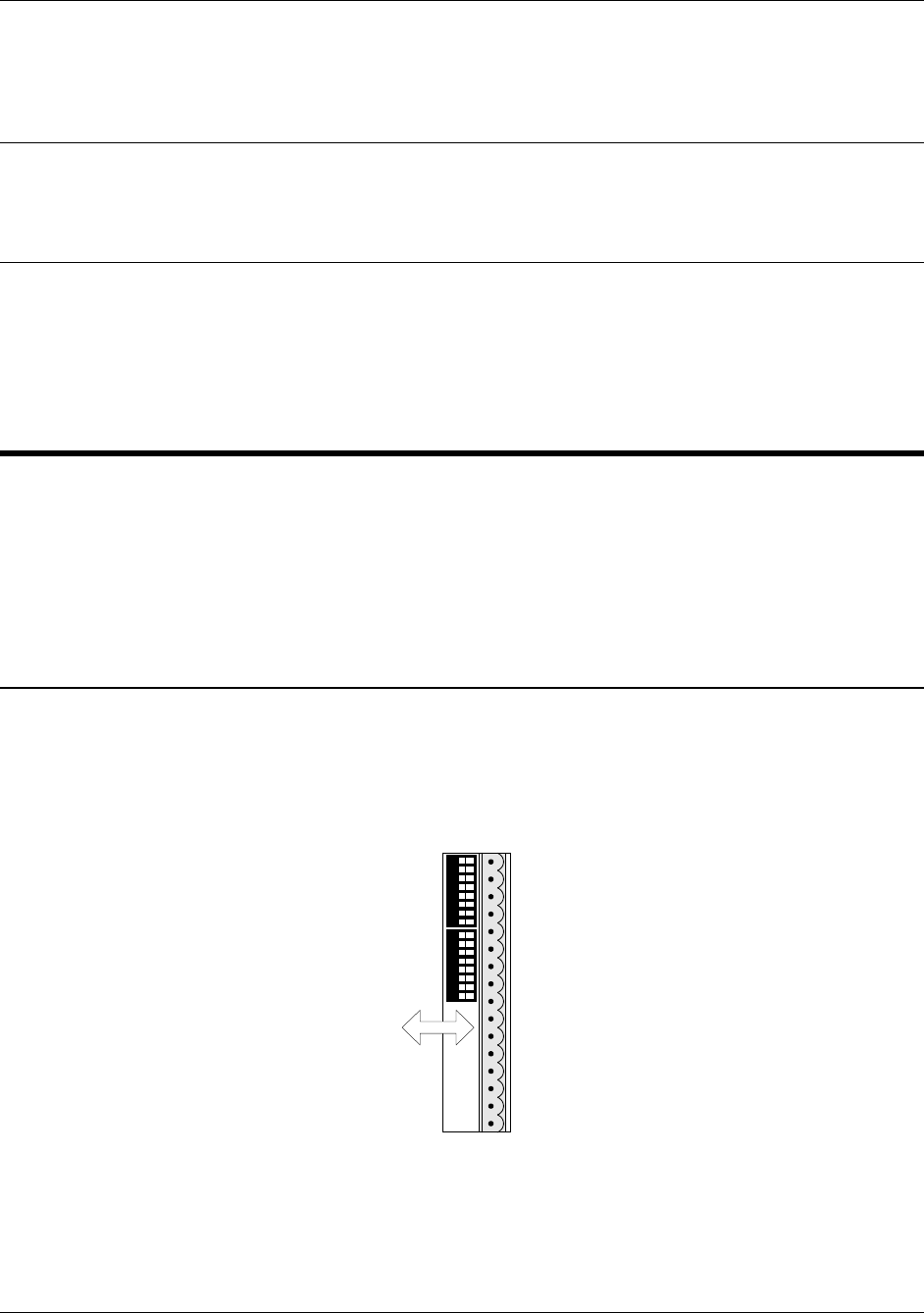
Removing the input connector reveals two banks of DIP switches as illustrated in the figure below. Each bank
has eight switches labeled 1 through 8 corresponding to inputs 1 through 8. The upper bank controls 200-ohm
shunt resistors (required for current monitoring applications) while the bottom bank controls pull-up resistors
(required for temperature monitoring and dry-contact applications.
12345678 12345678
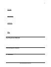
Input 1
Common
Input 2
Common
Input 3
Common
Input 4
Common
Input 5
Common
Input 6
Common
Input 8
Common
Input 7
Common
Shunt Resistors
Pull-Up Resistors
OFF ON


