5
www.remotepossibilities.com
Attach your dry contact sensor to the input screw terminals. Use the INP S command to configure the input for
a dry-contact sensor (refer to the Command Reference section).
TTL Logic
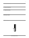
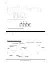
Flip to OFF the shunt resistor DIP switch for the input you want to modify and flip to OFF the pull-up resistor
DIP switch.
Attach the TTL sensor to the input screw terminals. Use the INP S command to configure the input for a dry-
contact sensor (refer to the Command Reference section).
Open Collector
Flip to OFF the shunt resistor DIP switch for the input you want to modify and flip to ON the pull-up resistor
DIP switch.
Attach the open-collector sensor to the input screw terminals. Use the INP S command to configure the input
for a dry-contact sensor (refer to the Command Reference section).
110/220 VAC
Caution: An interposing relay MUST be used to monitor 110/220 VAC signals.
Flip to OFF the shunt resistor DIP switch for the input you want to modify and flip to ON the pull-up resistor
DIP switch.
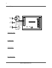
Wire the 110/220 VAC signal to the coil of a suitably rated relay. Wire the relay contacts to the input screw
terminals. Use the INP S command to configure the input for a dry-contact sensor (refer to the Command
Reference section).
Other
To connect a thermocouple, millivolt or other type sensor to the Messenger 570, use an appropriate signal
conditioner. Contact technical support for assistance.
Input Expansion Modules
Optional input expansion modules are available to expand the Messenger 570’s input monitoring capability to 32
inputs.
Each input expansion module accepts up to eight inputs and connects to the Messenger 570 via twisted pair cable.
Each module can be located up to 500 feet away from the Messenger 570.
Contact technical support for additional information.
Connecting the Outputs
The Messenger 570 has four outputs that can be controlled remotely or automatically in response to alarm
conditions or input parameters. The control capabilities of these outputs are described in the “Control” section of
this manual.
Output Relays
Each of the four outputs is capable of switching 5 amp loads. Note: When switching voltages in excess of 30
volts, the Messenger 570 must be placed in an approved enclosure.


