71
EN
Knowledge
section
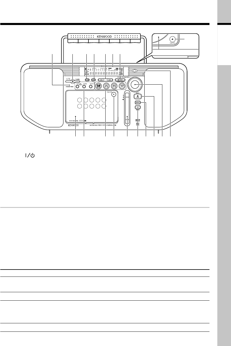
Controls and indicators
Main Unit
1 STANDBY/TIMER indicator (71)
2 POWER
3 SOUND (28)
4 AUX (18)
5 4, ¢ (Skip)
6 Display
7 7STOP/TUNING MODE (17)
8 CD door (10)
9 0PUSH OPEN(CD ejection)(10)
0 Cassette holder (14)
! BEST HITS (41)
MD REC (36)
TAPE REC (38)
@ TUNER FM/AM (8)
CD 6 (Play/ Pause) (10)
MD 6 (Play/ Pause) (12)
TAPE 23 (Play) (14)
# 0PUSH OPEN
(Tape ejection) (14)
$ MD insertion slot (12)
% SET/(DEMO) (6,7)
^ MENU (7)
& 0EJECT (MD ejection) (13)
* VOLUME/MULTI-CONTROL
( REMOTE (Remote sensor)
(4)
Figures inside parentheses are
reference pages.
APE T
9
2 3 4 5 6
8
1
$#@!0 %^&*(
7
Standby mode
While the standby indicator of the unit is lit, a small amount of current is flowing into the
unit’s internal circuitry to back up the memory. This condition is referred to as the standby
mode of the unit. While the unit is in the standby mode, it can be turned ON from the remote
control unit.
Relationship between the STANDBY/TIMER indicator and the status of unit
Indicator condition Unit status
Off Power is ON.
Red lighting The power cord is plugged into a wall outlet and the power is in the
STANDBY mode
Green lighting Timer has been activated.
Green blinking Timer setting is erroneous, an attempt is made to set the timer without
setting the time of the day, or the timer was not activated correctly due
to a power failure, etc.
Red blinking Failure in the power circuitry. Have your dealer service the unit.


