


11
Preparations
OperationsOther
KR-V999D (En/T)
VIDEO3
VIDEO4
VIDEO2
(OPTICAL)
AC-3
DIGITAL IN
AC-3 DIGITAL
OUTPUT
AC-3 RF
OFF ON
EXTERNAL DC SUPPLY DC 12V
INPUT
DC IN
12V
@ #
AC-3 DIGITAL
OUTPUT
AC-3 RF
OFF ON
INPUT
DC IN
12V
@ #
POWER LOCK
LASER DISC RF DEMODULATOR DEM-999D
21
POWER LOCK
LASER DISC RF DEMODULATOR DEM-999D
53 4 6
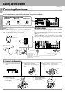
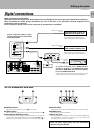
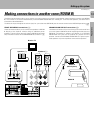
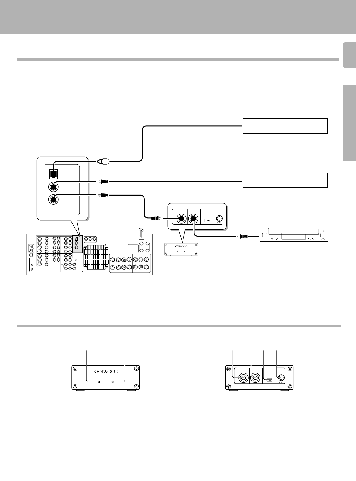
Make connections as shown below.
The digital in jacks can accept either Dolby Digital (AC-3) or PCM signals (the input signal type is detected automatically).
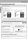
When connecting the related system components, be sure to also refer to the instruction manuals supplied with the
components you are connecting.
Do not connect the power cord to a wall outlet until all connections are completed.
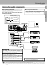
Digital connections
Setting up the system
Component with an AC-3 (or
PCM) COAXIAL DIGITAL OUT
COAXIAL DIGITAL OUT
(AUDIO)
Component with an AC-3 (or
PCM) OPTICAL DIGITAL OUT
OPTICAL DIGITAL OUT
(AUDIO)
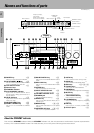
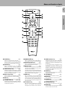
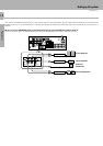
1 POWER indicator
Lights (red) when the power switch (5) is set to ON .
2 LOCK indicator
Lights when an AC-3 RF signal is input to the AC-3 RF INPUT jack (4).
3 AC-3 DIGITAL OUTPUT (coaxial)
Connect this jack to the coaxial AC-3 DIGITAL IN jack on your receiver.
It outputs AC-3 coaxial digital signals when the POWER (5) is set to
ON and an AC-3 RF signal is input to the AC-3 RF INPUT jack (4).
4 AC-3 RF INPUT
Connect this jack to the AC-3 RF OUTPUT jack on your LD player.
5 POWER switch
Use to switch the power ON/OFF.
6 DC IN (12V) jack
Connect this jack and inlet power cord to the AC adaptor supplied with
your demodulator. Connect the power cord to a wall outlet after
completing all of the other connections.
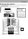
RCA pin cord
AC-3 RF OUT
(AUDIO)
To connect an LD player with a DIGITAL RF OUT.
Connect the LD player to the KENWOOD RF digital
demodulator (DEM-999D). Then connect the demodu-
lator to the VIDEO 4 DIGITAL IN.
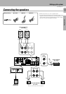
Connect the video signal and analog audio signals to the
VIDEO 4 jacks. (See "Connecting video components".)
Connect the video signal and analog
audio signals to the VIDEO 2 jacks.
(See "Connecting video components".)
Connect the video signal and analog
audio signals to the VIDEO 3 jacks.
(See "Connecting video components".)
Connect components capable of output-
ting Dolby Digital (AC-3) or standard PCM
format digital signals.
Place the power supply away from the demodulator,
receiver, and any antennas.
RCA pin cord
Optical fiber cable
AC-3 RF Demodulator DEM-999D
RCA pin cord