


VR*20_OiVR-208Q/KR_ V88Bl O/KRF V7 7710 {En/K]
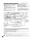
Make connections as shown below.
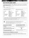
The digital in jacks can accept either DTS, Dolby Digital {AC-3) or PCM (CD Format) signals (the input signal type is detected
automatically).
When connecting the related system components, be sure to also refer to the instruction manuals supplied with the
components you are connecting.
Do not connect the power cord to a wall outlet until all connections are completed.
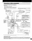
The connected components are given as examples because
the available models vary depending on marketing areas.
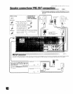
Connect components capable of output-
ting Dolby Digital IAC-3) or standard PCM
format digital signals.
LASER DISC RF DEMODULATOR (DEM-9991D)
Note : ©nlyrequi_edifyouwishtoplayLase_Discs
in the Dotby Digital (AC-3) format
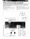
To connect an LD player with a Dolby Digital (AC-3) RF OUT or
DIGITAL OUT (Some LD player have a PCM Digital Outputs, in this case
the customer doesn't need the DEM-9991D,)
Connect the LD player to the {optional} KENWOOD LASER DISC RF
DEMODULATOR (DEM-9991D). Then connect the demodulator to
the DIGITAL IN (VIDEO4 COAXIAL),
To connect the digital output from an LD player, connect it either to
the DIGITAL INPUT OPT, (@_Jor DIGITAL INPUT COAX, ((_;) jack.
Connect the vdeo signal and analog audio signals to the V_DEO 4. jacks
(See "Connecting of video components")
ICOAXIAL) [ [_ r°_.,T-Si_7 i""I!I DGITALOUT i
| | (OP rlCALI
AC3 RF OuT
iCOAXIAL) Note : Connect either (_ or :_
Should not be corm acted both
_mlm
Q
DIGITAL. OUT_%
_C©AX/AL)
DrGITAL OUT 1_
[OPTICAL)
To connect an DVD player
with a DIGITAL OUT
=
Connect the video signal, S Video signa and
analog audio signals to the same serector
(INPUT) jacks,
(See "Connecting of video components" )
Use either the (i_ {COAXIAL) or _ (OPTICAL) jack for the connection of a DVD player,
To the VIDEO 4 COAXIAL jack, connect the input from the DIGITAL OUT (1_ (COAXIAL) jack of a OVD player or the DIGITAL
OUT (# (COAXIAL) Jack of the DEM-gg91D,
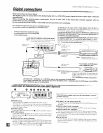
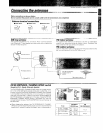
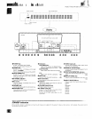
LASER DISC RF DEMODULATOR DEM-9991D (Optional)
Place the power supply away from the demodulator, receiver,
and any antennas.
0 POWER switch
Use to swtch the POWER OFF/POWER ON tOPTJCOAX,),
With the OPT or COAX, position, the input is switched automati-
cally to the Dolby Digital (AC-3) RF nput whenever the Dolby Digital
(AC-3) RF signal is inpuL
POWER indicator
Lghts (red) when the power switch (O) is set to ON (OPT/COAX t
RE LOCK indicator
lights when a Dolby Digital (AC-3) RF sgnal is input to the RF INPUT
_AC-3 RF INPUT} iack !_t. tThis ir,dicator is extinguished when a digital
input is in use.)
O DIGITAL OUTPUT COAX, (COAXIAL}
Connect this jack to the VIDEO4 COAXIAL (DIGITAL }Nt, jack On you_
Reeiever It outputs Dolby Digital (AC-3) coaxial digital signets when
the POWER (O) is set to COAX, and a Dolby Dig tel (AC-3) RF signal
is input to the RF tNPbT (AC*3 RE INPUT) iack (_)
RF INPUT AC-3 RF (Dolby Digital RF)
Connect this jack to the Dolby Dig tat (AC-3) RF OUTPUT jack on your
LD 0layer.
DIGITAL INPUT COAX, (COAXIAL)
Connect this jack to the COAXIAL OUTPUT iack on yo_,_ LD player
DIGITAL INPUT OPT, (OPTICAL)
Connect this iack to the OPTICAL OUTPLJT jack on your LD player,
• When there are simuhaneous inputs through the RF iNPUT tAC_3 RE)
iack and DIGITAL INPUT jack, the nput through RE INPUT (AC-3 RE) is
given the p_iodtv,
ODC tN 12V jack
Connect _hs iack to the AC adaptor suppled witr_ your demodulator
Connect the AC adaptor to a wail outlet after compJeting all of toe
other connections.