


32
Setting the Digital Input Terminals
—DIGITAL IN (7)
When you use the digital input
terminals, you have to register
what components you have
connected to the digital input
terminals.
7
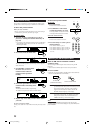
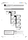
Setting the component connected to the digital
coaxial terminal
Set the component connected to the digital coaxial (DIGITAL
IN 1) terminal.
• Each time you press # (RIGHT) or @ (LEFT), the digital
component name changes as follows:
1DVD “ 1CD “ 1TV (or 1DBS* ) “ 1CDR “ 1MD**
“ (back to the beginning)
*
If you have changed the source name from “TV” to “DBS,”
“DBS” appears (see page 22).
**
If you want to connect an MD recorder to the digital input
terminal, change the source name to “MD” from “TAPE” (see
page 22).
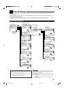
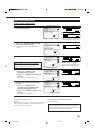
7
Setting the component connected to the digital
optical terminals
Set the components connected to the digital optical terminals.
• Each time you press # (RIGHT) or @ (LEFT), the digital
component names change as follows:
When “COAXIAL INPUT” is set to “DVD”
2 CD 3 TV (or DBS*) 4 CDR “
2 CD 3 TV (or DBS*) 4 MD** “
2 CD 3 MD** 4CDR “
2 MD** 3 TV (or DBS*) 4 CDR “
(back to the beginning)
When “COAXIAL INPUT” is set to “CD”
2 DVD 3 TV (or DBS*) 4 CDR “
2 DVD 3 TV (or DBS*) 4 MD** “
2 DVD 3 MD** 4CDR “
2 MD** 3 TV (or DBS*) 4 CDR “
(back to the beginning)
When “COAXIAL INPUT” is set to “TV” or “DBS”
*
2 CD 3 DVD 4 CDR “
2 CD 3 DVD 4 MD** “
2 CD 3 MD** 4 CDR “
2 MD** 3 DVD 4 CDR “
(back to the beginning)
When “COAXIAL INPUT” is set to “CDR”
2 CD 3 TV (or DBS*) 4 DVD “
2 CD 3 TV (or DBS*) 4 MD** “
2 CD 3 MD** 4 DVD “
2 MD** 3 TV (or DBS*) 4 DVD “
(back to the beginning)
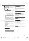
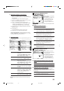
DIGITAL IN
COAXIAL INPUT: 1DVD
OPTICAL INPUT:
2CD 3TV 4CDR
:OPERATE
:BACK
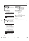
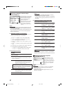
COMPONENT IN
COMPONENT INPUT:
1DVD 2–––
:OPERATE
:BACK
When “COAXIAL INPUT” is set to “MD”
**
2 CD 3 TV (or DBS*) 4 CDR “
2 CD 3 TV (or DBS*) 4 DVD “
2 CD 3 DVD 4 CDR “
2 DVD 3 TV (or DBS*) 4 CDR
(back to the beginning)
*
If you have changed the source name from “TV” to “DBS,”
“DBS” appears (see page 22).
**
If you have connected an MD recorder to the digital input
terminal, change the source name to “MD” from “TAPE” (see
page 22).
Note:
When shipped from the factory, the DIGITAL IN terminals can be used
as the digital input for the following components:
• DIGITAL 1 (coaxial): For DVD player
• DIGITAL 2 (optical): For CD player
• DIGITAL 3 (optical): For digital TV broadcast tuner
• DIGITAL 4 (optical): For CD recorder
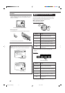
Preparing for the Component Video Input
—COMPONENT IN (8)
When you use the component
video input, you have to register
what components you have
connected to the component
input terminals.
Without setting this correctly,
you cannot view the correct input
on the TV.
7
Setting the component video input terminals
Select the components connected to the COMPONENT 1
(DVD) and COMPONENT 2 video input terminals.
• Each time you press # (RIGHT) or @ (LEFT), the component
name changes as follows:
1 DVD 2 – – – “ 1 DVD 2 DBS* “
1 DVD 2 VCR1 “ 1 DBS* 2 – – – “
1 DBS* 2 VCR1 “ 1 VCR1 2 – – – “
1 – – – 2 – – – “ (back to the beginning)
Notes:
*
When you have connected the DBS tuner to the COMPONENT
1 (DVD) or COMPONENT 2 video input terminals, change the
source name from “TV” to “DBS.”
To change the source name, see “Changing the Source Name”
on page 22.
• When you have not connected any component, select “– – –.”
• If you have not made this setting correctly, the AV COMPU LINK
remote control system cannot operate properly. (See page 53.)
EN26-33_RX-DP9VBK[J]_f 01.6.14, 9:53 AM32