51
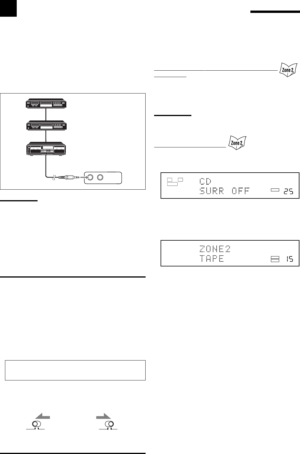
To use this remote control system, you need to connect JVC’s audio
components through the COMPU LINK (SYNCHRO) jacks (see
below) in addition to the connections using cables with RCA pin
plugs (see pages 10 and 11).
• Make sure that the AC power cords of these components are
unplugged before connection. Plug the AC power cords only after
all connections are complete.
Notes:
• There are four versions of COMPU LINK remote control system.
This receiver is equipped with the fourth version—COMPU LINK-4.
This version is added systematic operations with the CD recorder to
the previous version—COMPU LINK-3.
• If your audio component has two COMPU LINK jacks, you can use
either one. If it has only one COMPU LINK jack, connect it so that it
is the last item in the series of components.
• To operate the cassette deck or MD recorder using the COMPU
LINK remote control system, set the source name correctly if
required. (See page 24.)
• Refer also to the manuals supplied for your audio components.
COMPU LINK-4
(SYNCHRO)
COMPU LINK Remote Control System
The COMPU LINK remote control system allows you to operate JVC’s audio components through the remote sensor on
the receiver.
• Refer also to the manuals supplied with your audio components.
This remote control system allows you to use four functions listed
below.
Remote Control through the Remote Sensor on
the Receiver
You can control the connected audio components through the remote
sensor on the receiver using this remote control. Aim the remote
control directly at the remote sensor on the receiver. For details,
see pages 56 and 57.
Note:
When using RF rod antenna (see page 14), it is unnecessary for
aiming directly at the remote sensor on the receiver.
Automatic Source Selection
• When you press the play (3) button on a connected component or
on its own remote control, the receiver automatically turns on and
changes the Zone 1 source to the component.
– If the receiver is already turned on with the ZONE 2 indicator
lights up and the source name for Zone 2 appears on the unit‘s
display, the receiver changes the Zone 2 source to the
component.
• When you press PLAY on the remote control supplied for this
receiver, the receiver automatically turns on and changes the Zone
1 source or Zone 2 source to the target component, depending on
ZONE 1/ZONE 2 selector setting on the remote control.
• When you select a new source on the receiver or on the remote
control supplied for this receiver either for Zone 1 or Zone 2, the
newly selected component begins playing immediately, and the
previously selected source continues playing without sound for a
few seconds.
CD player
CD recorder
Cassette deck
or
MD recorder
IMPORTANT:
Check the following before or while using the buttons and controls.
For Zone 1 operations:
The ZONE 1 indicator lights up on the unit’s display.
For Zone 2 operations:
The ZONE 2 indicator lights up on the unit’s display.
• When using the unit:
–For Zone 1 operations: “ZONE2” is not shown in the unit’s main
display.
–For Zone 2 operations: “ZONE2” is shown in the unit’s main
display.
• When using the remote control:
When operating the receiver using the remote control, the
unit’s display always shows the Zone 1 source information
though you are operating it for the Zone 2 source.
–Set the ZONE 1/ZONE 2 selector to ZONE 1 or ZONE 2 correctly.
–Check the indication shown on the remote’s display when you
press a button—this indicates the remote control operation mode
together with multi-room operation mode (either for ZONE 1 or
ZONE 2) for about two hours.
ZONE 2
ZONE 1
ZONE 2
ZONE 1
LINEAR PCM
L
SUBWFR
R
ANALOG
VOLUME
SPEAKERS 1
ZONE 1
LINEAR PCM
VOLUME
SPEAKERS 1 ZONE 2
ZONE 1
ZONE 2
Ex. When you operate the CD player for Zone 1
Ex. When you operate the cassette deck for Zone 2
Ex. When you set ZONE 1/
ZONE 2 selector to ZONE 1.
Ex. When you set ZONE 1/
ZONE 2 selector to ZONE 2.


