


10
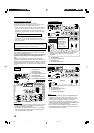
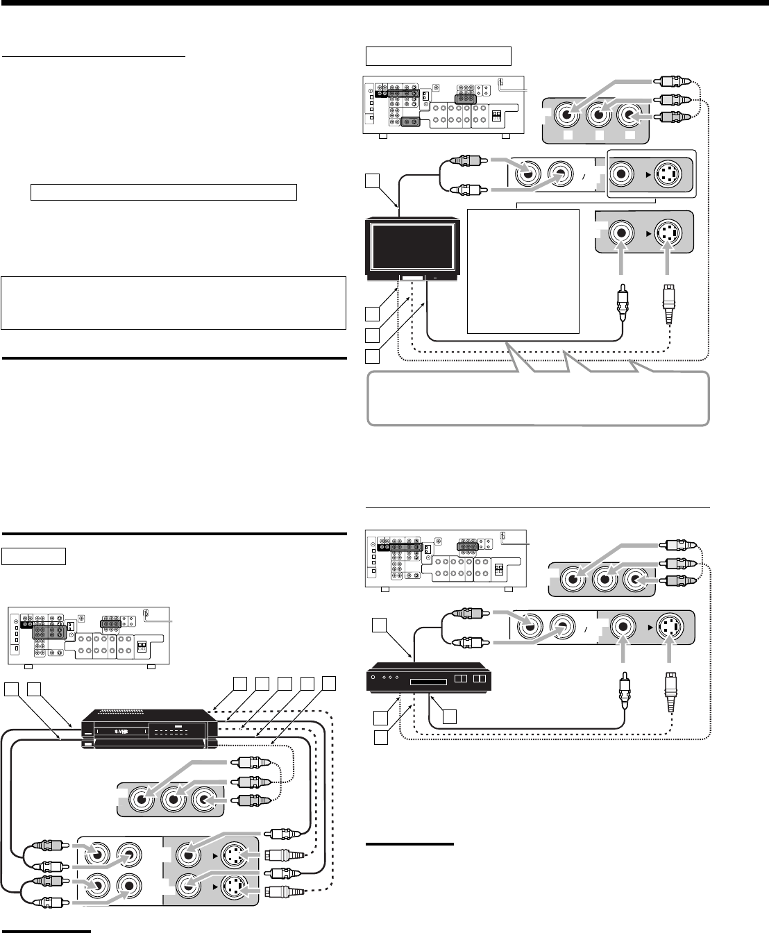
Video component connections
Use the cables with RCA pin plugs (not supplied).
Connect the white plug to the audio left jack, the red plug to the
audio right jack, and the yellow plug to the video jack.
• If your video components have S-video (Y/C-separation) and/or
component video (Y, PB, PR) terminals, connect them using an S-
video cable (not supplied) and/or component video cable (not
supplied). By using these jacks, you can get better picture quality
in the order:
Component video > S-video > Composite video
• If your video components have digital audio output terminal,
connect them using the digital cords explained in “Digital
connections” (see page 12). By using this terminal, you can get
better sound quality.
If your video components have an AV COMPULINK jack
See also page 38 for detailed information about the connection
and the AV COMPU LINK remote control system.
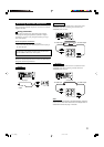
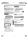
IMPORTANT:
This receiver is equipped with the following video jacks—composite
video, S-video and component video jacks. You can use any of the
three to connect a video component.
However, the video signals from one type of these input jacks are
transmitted only through the video output jacks of the same
type.
Therefore, if a recording video component and a playing video
component are connected to the receiver through the video jacks of
different type, you cannot record the picture. In addition, if the TV and
a playing video component are connected to the receiver through the
video jacks of different type, you cannot view the playback picture on
the TV.
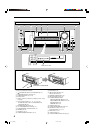
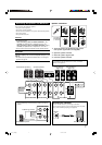
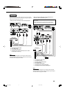
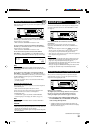
VCR
ÅTo audio input
ıTo audio output
ÇTo S-video output
ÎTo composite video output
‰To S-video input
ÏTo composite video input
ÌTo component video output
Notes:
• When connecting a VCR to component video input jacks, make the
component video input setting (VIDEO IN VCR) correctly for AV
COMPU LINK. See page 26 for details.
• When make the component video input setting for a VCR (VIDEO
IN VCR) correctly, the component video input setting for a DBS
tuner (VIDEO IN DBS) is not available.
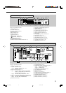
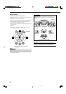
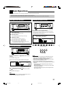
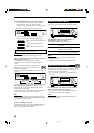
VCR
TV and/or DBS tuner
Å To audio output
ı To component video input
Ç To S-video input
Î To composite video input
Å To audio output
ı To component video output
Ç To S-video output
Î To composite video output
Notes:
• When connecting a DBS tuner to the TV SOUND/DBS IN jacks,
change the source name to “DBS,” which will be shown on the
display when it is selected as the source. Otherwise you cannot
view any picture from DBS tuner. See page 17 for details.
• When connecting a DBS tuner to component video input jacks,
make the component video input setting (VIDEO IN DBS) correctly
for AV COMPU LINK. See page 26 for details.
• When make the component video input setting for a DBS tuner
(VIDEO IN DBS) correctly, the component video input setting for a
VCR (VIDEO IN VCR) is not available.
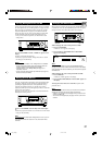
MONITOR
OUT
TV SOUND
DBS
IN
MONITOR
OUT
Y
P
B
P
R
A
B
C
D
R
L
TV
When connecting
the TV to the
AUDIO jacks (TV
SOUND/DBS IN),
DO NOT connect
the TV’s video
output to these
video input jacks.
Connect the TV to appropriate MONITOR OUT jacks to view
the playback picture from any other connected video
components.
TV SOUND
DBS
IN
DBS
(
VCR
)
IN
A
B
C
D
R
L
DBS
DBS tuner
VCR
IN
(PLAY)
OUT
(REC)
A B
D
C
E
F
R
L
R
L
G
DBS
(
VCR
)
IN
01-12_7040[J] 04.1.21, 15:5410