


11
Getting to Know the AV Receiver
—Continued
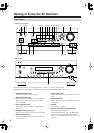
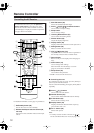
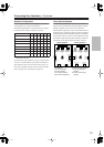
E
ETHERNET
This port is for connecting the AV receiver to home
automation equipment and external controllers. Use
only shielded Ethernet cables.
F
MONITOR OUT
The S-Video or composite video jack should be
connected to a video input on your TV or projector.
G
SIRIUS antenna (on North American model)
This jack is for connecting a SIRIUS digital
antenna, sold separately (see the separate SIRIUS
instructions).
H
FM ANTENNA
This jack is for connecting an FM antenna.
I
AM ANTENNA
These push terminals are for connecting an AM
antenna.
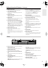
J
IR IN A/B and OUT
A commercially available IR receiver can be con-
nected to the IR IN A or B jack, allowing you to
control the AV receiver while you’re in Zone 2, or
control it when it’s out of sight, for example,
installed in a cabinet.
A commercially available IR emitter can be con-
nected to the IR OUT jack to pass IR (infrared)
remote control signals through to other components.
K
12V TRIGGER OUT (A/B/C)
These outputs can be connected to the 12-volt trig-
ger inputs on other components.
L
RS232
This port is for connecting the AV receiver to home
automation equipment and external controllers.
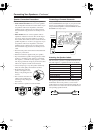
M
ZONE 2 PRE OUT L/R
These analog audio outputs can be connected to the
line inputs on amplifiers in Zone 2.
N
ZONE 2 SPEAKERS L/R
These terminal posts are for connecting speakers in
Zone 2.
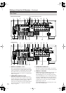
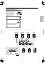
O
DIGITAL OPTICAL IN 1, 2, and OUT
These optical digital audio inputs are for connecting
components with an optical digital audio output,
such as a CD player or DVD player. They’re assign-
able, which means you can assign each one to an
input selector to suit your setup. See “Digital Input
Setup” on page 45.
The optical digital audio output is for connecting a
digital recorder with an optical digital input, such as
a CD recorder.
P
REMOTE CONTROL
This (Remote Interactive) jack can be connected
to the jack on another -capable Integra/
Onkyo component for remote and system control.
To use , you must make an analog audio connec-
tion (RCA) between the AV receiver and the other
component, even if they are connected digitally.
Q
CD IN
This analog audio input is for connecting a CD
player’s analog audio output.
R
TAPE IN/OUT
These analog audio input and output jacks are for
connecting a recorder with an analog audio input
and output, such as a cassette deck, MD recorder,
etc.
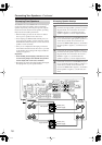
S
GAME/TV IN
A game console or TV output can be connected
here. There’s S-Video and composite video input
jacks for connecting the video signal.
T
CBL/SAT IN
A cable or satellite receiver can be connected here.
There are S-Video and composite video input jacks
for connecting the video signal, and there are analog
audio input jacks for connecting the audio signal.
U
VCR/DVR IN/OUT
A video component, such as a VCR or DVR, can be
connected here for recording and playback. There
are S-Video and composite video input and output
jacks for connecting the video signal, and there are
analog audio input jacks for connecting the audio
signal.
V
DVD IN
This input is for connecting a DVD player. There
are S-Video and composite video input jacks for
connecting the video signal.
W
DVD FRONT L/R, CENTER, SUBWOOFER,
SURR L/R, and SURR BACK L/R
This analog multichannel input is for connecting a
component with a 5.1/7.1-channel analog audio out-
put, such as a DVD player, DVD-Audio or
SACD-capable player, or an MPEG decoder.
X
PRE OUT: FRONT L/R, CENTER, SUB-
WOOFER, SURR L/R, and SURR BACK L/R
This 5.1/7.1 multichannel analog audio output can
be connected to the analog audio input on a multi-
channel power amplifier for when you want to use
the AV receiver solely as a preamplifier. The SUB-
WOOFER jack is for connecting a powered sub-
woofer.
Y
FRONT L/R, CENTER, SURR L/R, and SURR
BACK L/R SPEAKERS
These terminal posts are for connecting the front
speakers, center, surround, and surround back
speakers.
Z
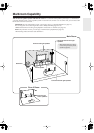
AC INLET
The supplied power cord is connected here. The
other end of the power cord should be connected to
a suitable wall outlet.
See pages 14–37 for hookup information.