


28
INSTALLATION
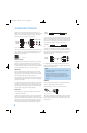
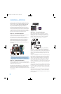
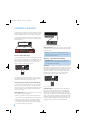
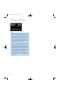
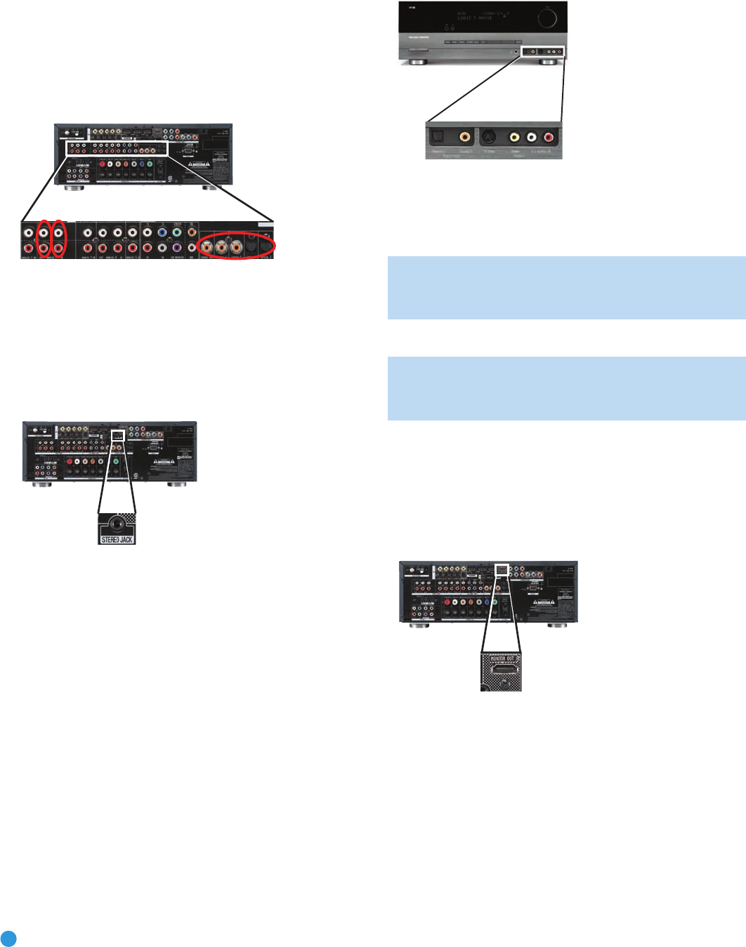
To make analog audio recordings, connect the recorder’s left and right
analog audio outputs to the Analog 2 Audio Inputs on the AVR, and the
recorder’s analog audio inputs to the AVR’s Analog 2 Audio Outputs.
No video connection is required, although the AVR will display any signal
at the video input assigned to the same source as the Analog 2 Audio
Inputs. See Figure 29.
Figure 29 – Connecting an Audio Recorder
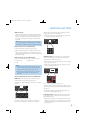
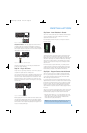
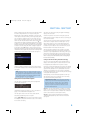
Connect a Portable Audio Player
For audio-only playback from a portable CD player, cassette deck, MP3
player or other device equipped with a 1/8-inch headphone jack, use
a stereo 1/8-inch mini-plug interconnect (not included) to connect the
device’s headphone jack to the Stereo Jack on the AVR. Use the
device’s own controls to operate it. See Figure 30.
Figure 30 – Connecting a Portable Audio Player
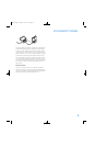
Alternatively, use an interconnect with a stereo 1/8-inch mini-plug at
one end and two RCA plugs at the other end to connect the player to
the Audio Inputs on the AVR’s front panel. See Figure 31.
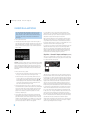
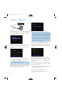
Connecting a Game Console, Camera or Other Device
If a device will only be connected temporarily, you may use the audio/
video inputs on the front panel. When not in use, place the supplied
covers over the jacks for a cleaner appearance by snapping the covers
in place. To remove the covers, gently press on the left side of each
cover so that it pivots out.
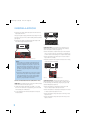
Video Components: Install video components, e.g., game consoles
and camcorders, as follows (see Figure 31):
• Connect the component’s S-video or composite video output (use
only one connection) to the corresponding front-panel Input on the AVR.
• Connect the component’s optical or coaxial digital audio output to
either the Optical or Coaxial Input on the front panel (if available).
For fully analog devices, connect the device’s analog audio outputs
to the AVR’s front-panel Analog Audio Inputs.
Figure 31 – Connecting a Device to the Front-Panel Inputs
Audio Components: Connect audio-only devices, such as CD players,
to either the Coaxial or Optical Digital Audio Inputs, or the Analog Audio
Inputs (see Figure 31).
NOTE: If your video devices are equipped with HDMI or com-
ponent video outputs, you may connect them to any available
audio and video input on the AVR.
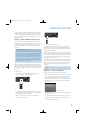
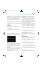
Step Five – Connect the Video Display
IMPORTANT NOTE: Do not connect any video output on the
video display (TV) to any video input on the AVR. Doing so will
cause undesirable video interference.
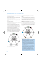
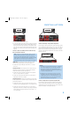
HDMI Video: If the display has an HDMI input, connect the HDMI
Monitor Output to the display (see Figure 32). Thanks to the AVR 254’s
sophisticated video processing and upscaling capabilities, no other video
connections are required from the AVR to the video display. Analog
video sources (composite, S-video and component) are converted to
the HDMI format and upscaled to as much as 1080p resolution,
depending on the display’s capabilities. Proceed to Step Six.
Figure 32 – HDMI Monitor Output
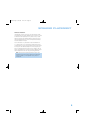
Component Video: If the display does not have HDMI inputs, but
does have component video inputs, connect the Component Video
Monitor Outputs to the display (see Figure 33). As with HDMI connec-
tions, the AVR 254 is capable of converting composite and S-video
sources to the component video format, while upscaling the resolution to
as high as 1080i, depending on the display’s capabilities. Unlike HDMI
connections, component video connections do not enable the AVR 254
to detect the display’s capabilities and the appropriate resolution must
be selected manually, as described in the Initial Setup section.
AVR 254
AVR 254
AVR 254
AVR 254
AVR254om.qxd 3/28/08 12:46 PM Page 28