


11
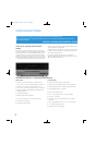
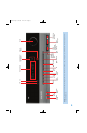
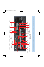
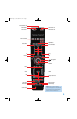
REAR-PANEL CONNECTIONS
AM and FM Antenna Terminals: Connect the included AM
and FM antennas to their respective terminals for radio reception.
XM Antenna Jack: Plug in an XM Connect and Play or Mini Tuner
antenna module here. The XM antenna module is purchased separately,
and should specify that it is for home use with an XM Ready
®
product.
You will need to subscribe to the XM service, which is available sepa-
rately, and activate the service for your antenna module. (XM service
is not available in Alaska and Hawaii.)
Front, Center and Surround Speaker Outputs: Use two-
conductor speaker wire to connect each set of terminals to the correct
speaker. Remember to observe the correct polarity (positive and negative
connections). Always connect the positive lead to the colored terminal
on the receiver and the red terminal on the speaker. Connect the negative
lead to the black terminal on both the receiver and the speaker. See the
Connections section for more information on connecting your speakers.
Surround Back/Zone 2 Speaker Outputs: These speaker
outputs are used for the surround back channels in a 7.1-channel home
theater, or may be reassigned to a remote room for multizone operation.
When these outputs are reassigned for multizone operation, only a
5.1-channel configuration will be available in the main listening room.
Use the on-screen menu system to configure these channels as desired.
As with the other speaker outputs, remember to observe proper polarity
by connecting the positive and negative output terminals to the corre-
sponding terminals on each speaker.
Subwoofer Output: If you have a powered subwoofer with a
line-level input, connect it to this jack.
Preamp Outputs: Connect these jacks to an external amplifier if
more power is desired.
The Surround Back/Zone 2 Preamp Outputs may be used with an
external amplifier to power the surround back channels, or to power
the remote zone of a multizone system. Use the on-screen menu
system to configure these channels as desired.
Remote Infrared (IR) Input and Output: When the remote IR
receiver on the front panel is blocked, such as when the AVR is placed
inside a cabinet, connect an optional IR receiver to the Remote IR Input
jack for use with the remote control. The Remote IR Output may be
connected to the Remote IR Input of a compatible product to enable
remote control through the AVR. This is particularly useful in multizone
applications to control a source device from the remote room (when
used with the Zone 2 IR Input). When several source devices are used,
connect them in “daisy chain” fashion.
Zone 2 Infrared (IR) Input: Connect a remote IR receiver located
in the remote zone of a multizone system to this jack to control the AVR
(and any source devices connected to the Remote IR Output) from the
remote zone.
Composite and S-Video 1, 2 and 3 Video Inputs: These
jacks may be used to connect your video-capable source components
(e.g., VCR, DVD player, cable TV box) to the receiver. Use only one type
of video connection for each source. These inputs are assignable, which
means they may be paired with any analog or digital audio inputs. This
will be explained in more detail in subsequent sections of this manual.
NOTE: The Video 2 inputs are associated with a set of outputs.
Consider connecting a video recorder here.
Composite and S-Video 2 Outputs: Connect one of these
analog video outputs to the composite or S-video inputs of a recording
device. A signal is available at these outputs whenever an analog video
source is playing. HDMI and component video signals are not available
for recording.
Composite and S-Video Monitor Outputs: If any of your
sources use composite or S-video connections, connect one or both of
these monitor outputs to the corresponding inputs on your television or
video display. If your video display is equipped with HDMI or component
video inputs, these connections are unnecessary. Connect the HDMI
Monitor Output (if available, otherwise use the Component Video Monitor
Output) to your TV, and the AVR 254 will convert the composite or
S-video source signal to the correct format for a single video cable
connection to the TV.
HDMI Inputs and Output: HDMI (High-Definition Multimedia
Interface) is a connection for transmitting digital audio and video signals
between devices. With the AVR 254’s powerful processor, you may
connect up to three HDMI-equipped source devices to the HDMI inputs
using a single-cable connection, while benefiting from superior digital
audio and video performance. If your video display is not HDMI-compatible,
connect the device to one of the analog video inputs, then pair it with
an analog or digital audio input.
If your video display has an HDMI input, make just the HDMI video con-
nection to your display; the AVR 254 will automatically transcode analog
video signals to the HDMI format, upscaling to as high as 1080p.
Analog 1 – 5: Connect the left and right analog audio outputs of
a source device to any of these inputs. These inputs are assignable,
which means they may be paired with any video inputs, as explained
in subsequent sections of this manual.
NOTES:
• The Analog 3 through 5 connectors physically line up below
the Video 1 through 3 (composite and S-video) connectors.
For convenience, consider using Analog 3 with Video 1, Analog 4
with Video 2 and Analog 5 with Video 3, if appropriate for
your system.
• The Analog 1 and 2 connectors don’t physically line up with
any analog video inputs. Consider using them for audio-only
devices, such as a CD player or cassette tape deck.
• The Analog 2 and 4 inputs are each associated with a set of
outputs. Consider using the Analog 2 connectors for an audio
recorder, and the Analog 4 connectors for a video recorder
(along with the Video 2 connectors).
• You may optionally connect a source to both an analog and
digital audio input. This is useful for making recordings, for
multizone applications or simply as a backup.
AVR254om.qxd 3/28/08 12:45 PM Page 11