


8
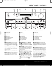
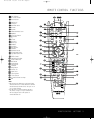
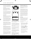
REAR-PANEL CONNECTIONS
REAR-PANEL CONNECTIONS
minal is the positive, or “+,” terminal that should be
connected to the red (+) terminal on the Surround
Back speaker with older color-coding. Connect the
black (–) ter
minal on the AVR to the matching black
negative (–) ter
minal on the surround back speaker.
(See page 12 for more information on speaker
polarity.)
• Surround Speaker Outputs: Connect these out-
puts to the matching + and – terminals on your sur-
round channel speakers. In conformance with the CEA
color-code specification, the blue terminal is the posi-
tive, or “+,” terminal that should be connected to the
red (+) terminal on the Surround Left speaker with
older color
-coding, while the gray terminal should be
connected to the red (+) terminal on the Surround
Right speaker with the older color-coding. Connect the
black (–) terminal on the AVR to the matching black
negative (–) terminals for each surround speaker. (See
page 12 for more information on speaker polarity.)
ª Center Speaker Outputs: Connect these outputs
to the matching + and – terminals on your center
channel speaker. In conformance with the CEA
color-code specification, the green terminal is the
positive, or “+,” terminal that should be connected to
the red (+) terminal on speakers with the older color-
coding. Connect the black (–) terminal on the AVR to
the black (–) terminal on your speaker. (See page 12
for more information on speaker polarity.)
‚ Component Video Monitor Outputs: Connect
these outputs to the component video inputs of a
video projector or monitor. When a source connected
to one of the
Component Video Inputs ⁄¤ is
selected, the signal will be sent to these jacks.
⁄ Video 2 Component
Video Inputs:
Connect the
Y/Pr/Pb component video outputs of an HDTV set-top
converter, satellite receiver or other video source
device with component video outputs to these jacks.
¤ DVD Component
Video Inputs:
Connect the
Y/Pr/Pb component video outputs of a DVD player to
these jacks.
‹ AC Power Cord: Connect the AC power cord to a
non-switched AC wall outlet.
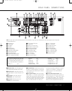
› Switched AC Accessory Outlet:These outlets
may be used to power any device you wish to have
turned on when the AVR 135 is turned on.
fi Unswitched AC Accessory Outlet: This outlet
may be used to power any
AC device.The power will
remain on at this outlet regardless of whether the
AVR 135 is on or off.
NOTE: The total power consumption of all devices
connected to the accessor
y outlets should not exceed
100 watts.
fl Optical Digital
Audio Output:
Connect this jack
to the optical digital input connector on a CD-R/RW,
MiniDisc or other digital recorder.
‡ Coaxial Digital Audio Output: Connect this jack
to the coaxial digital input of a CD-R/RW, MiniDisc or
other digital recorder.
° S-Video Monitor Output: If any of the input
sources used in your system have S-video connec-
tions to the AVR, connect this jack to the S-video input
on your television,
projector or other video display.
· Coaxial Digital Audio Inputs: Connect the coax
digital output from a DVD player
, HDTV receiver,
LD
player
or CD player to these jacks.The signal may be a
Dolby Digital signal, DTS signal or a standard PCM digital
source. Do not connect the RF digital output of an LD
player to these jacks.
a DVD S-Video Input: Connect the S-video output of
a DVD player or other video source to this jack.
b Video 1 S-Video Input: If the product connected to
the
Video 1 Audio Inputs i has S-video capability,
connect this jack to the PLAY/OUT S-video jack on
that unit and then make certain that the
S-Video
Monitor Output
° is connected as described
above.
c Optical Digital Audio Inputs: Connect the optical
digital output from a DVD player, HDTV receiver, LD
player or CD
player to these jacks.The signal may be a
Dolby Digital signal, a DTS signal or a standard PCM
digital source.
d Video 1 S-Video Output: If the product connected
to the
Video 1 Audio/Video Outputs j has S-video
capability, connect this jack to the REC/IN S-video jack
on that unit.
e Video 2 S-Video Input:If
the product connected
to the
Video 2 Audio/Video Inputs k has S-video
capability, connect this jack to the PLAY/OUT S-video
jack on that unit and then make certain that the
S-Video Monitor Output ° is connected as
described above
.
f 6/8-Channel Direct Inputs: These jacks are
used for connection to source devices such as DVD-
Audio or SACD players with discrete analog outputs.
Depending
on the source device in use
,
all eight jacks
may be used, though in many cases only connections
to the front left/right, center, surround left/right and
LFE (subwoofer input) jacks will be used for standard
5.1 audio signals
.
g Video Monitor Output: Connect this jack to the
composite video input of a TV monitor or video projec-
tor to view the on-screen menus and the output of a
standard video source.
h DVD
Audio/Video Inputs:
Connect the composite
video and L/R analog audio outputs of a DVD player or
other video source to these jacks.
i Video 1 Audio/Video Inputs: Connect the com-
posite or Video and L/R analog audio PLAY/OUT jacks
of a VCR or other video source to these jacks.
j Video 1 Audio/Video Outputs: Connect the
composite or Video and L/R analog audio REC/IN
jacks of a VCR or other video recording device such
as a DVD recorder or PVR to these jacks
.
k Video 2 Audio/Video Inputs: Connect the com-
posite or
Video and L/R analog audio PLAY/OUT jacks
of a cable television box or other video source to
these jacks.
z
AM Antenna Terminals: Connect theAM loop
antenna supplied with the receiver to these terminals.
If an externalAM antenna is used, make connections
to the
AM and GND terminals in accordance with
the instructions supplied with the antenna.
Note on video connections: When connecting a
video source product such as a VCR, DVD player,
satellite receiver, cable set-top box, personal video
recorder or video game to the AVR 135, you may
use either a composite or S-video connection,
but not both.
33
3
4
35
3
6
37
3
8
39
4
0
41
48
49
46
47
44
45
42
43
38
39
40
4
1
31
32
30
28
29
25
2
6
2
7
28
29
30
24
2
3
22
21
20
3
1
3
7
3
6
35
34
33
3
2
31
3
7
36
35
34
3
3
3
2
48
49
50
5
1
4
7
46
45
44
4
3
4
2
REAR-PANEL CONNECTIONS
8
REAR-PANEL CONNECTIONS
AVR 135 OM 12/3/04 12:11 PM Page 8