


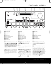
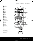

8 Surround Mode Selector: Press this button
to select from among the available surround mode
options for the mode group selected.The specific
modes will vary based on the number of speakers
available
, the mode group and if the input source is
digital or analog. For example, press the
Surround
Mode Group Selector
7 to select a main mode
grouping such as Dolby or Logic 7, and then press
this button to see the specific mode choices available
.
F
or more information on mode selection, see page 22.
9 Tuning Selector: Press the left side of the button
to tune lower-frequency stations and the right side of
the button to tune higher-frequency stations.When the
tuner is in the Manual mode, each tap will increase or
decrease the frequency by one increment.When the
tuner receives a strong enough signal for adequate
reception,
MANUAL TUNED will appear in the
on-screen display and the
Lower Display Line ¯.
When the tuner is the Auto mode, press the button
once, and the tuner will scan for a station with accept-
able signal strength.
When the next station with a
strong signal is tuned the scan will stop and the
on-screen display and
Lower Display Line ¯
will indicate AUTO TUNED.When an FM
Stereo station is tuned, the display will read
AUTO ST TUNED.
To switch back and forth between the Auto and
Manual tuning modes, press the
Tuner Mode
Selector
&.
) ‹/› Buttons: When configuring the AVR 135’s
settings, use these buttons to select from the available
choices
.
! Tuner Band Selector: Press this button to turn
the AVR on and to select the Tuner as the input. Press
it again to switch between the AM and FM frequency
bands
.
(See page 26 for more infor
mation on the tuner
.)
@ Set Button: When making choices during the
setup and configuration process
,
press this button
to enter the desired setting into the AVR 135’s memory.
# Digital Input Selector: Press this button to
select one of the digital inputs or the analog input for
any source. (See pages 23–26 for more information
on digital audio.)
$ Preset Stations Selector: Press this button to
scroll up or down through the list of stations that have
been entered into the preset memory. (See page 27
for more infor
mation on tuner presets
.)
% Delay Adjust Selector: Press this button to
begin the steps required to enter delay settings. (See
pages 19–20 for more information on delay times.)
^ Input Source Selector: Press this button to
change the input by scrolling up or down through the
list of
Input Indicators ı.
& Tuner Mode Selector: Press this button to select
Auto or Manual tuning.When the button is pressed so
that the
AUTO appears in the Lower Display Line
¯, the tuner will search for the next station with an
acceptable signal when the
T
uning Selector
9u
is pressed.When the button is pressed so that
MANUAL appears in the Lower Display Line ¯,
each press of the
Tuning Selector 9u will
increase the frequency
.This button may also be used to
switch between Stereo and Mono modes for FM radio
reception.When weak reception is encountered, press
the button so that
MANUAL appears in the Lower
Display Line
¯ and on the on-screen display to
switch to Mono reception. Press it again to switch back
to Stereo mode. (See page 26 for more information on
using the tuner.)
* Optical 3 Digital Audio Input: Connect the optical
digital audio output of an audio or video product to this
jack.When the input is not in use, be certain to keep
the plastic cap installed to avoid dust contamination that
might degrade future performance.
( Coaxial 3 Digital Audio Input: This jack is used
for connection to the output of portable audio devices,
video game consoles or other products that have a
coax digital audio jack.
Ó Video 3 Video Input Jacks: These jacks may
be used for temporary connection to the composite or
S-video output of video games, camcorders or other
portable video products.You may make a connection
to either jack at any time
,
but not to both simultaneously
.
Ô Video 3 Audio Input Jacks: These audio jacks
may be used for temporary connection to video
games or portable audio/video products such as
camcorders and portable audio players.
Bass Control: Turn this control to modify the low-
frequency output of the left/right channels by as much
as
±
10dB.
Ò Balance Control: Turn this control to change the
relative volume for the front left/right channels.
NOTE: For proper operation of the surround modes
this control should be at the midpoint or “12 o’clock”
position.
ÚTreble Control: Turn this control to modify the high
frequency output of the left/right channels by as much
as ±10dB.
Û Channel
Adjust Selector:
Press this button to
begin the process of trimming the channel output lev-
els using an external audio source. (For more informa-
tion on output level trim adjustment, see page 27.)
Ù Volume Control: Turn this knob clockwise to
increase the volume, counterclockwise to decrease the
volume. If the AVR 135 is muted, adjusting the
V
olume Control
Ù will automatically release
the unit from the silenced condition.
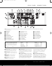
ı Input Indica
tors:
The current selected source will
appear as one of these indicators. Note that when the
unit is turned on, the entire list of available modes will
light briefly, and then revert to normal operation with
only the active mode indicator illuminated.
ˆ Speaker/Channel Input Indicators: These indi-
cators are multipurpose, indicating both the speaker
type selected for each channel and the incoming data-
signal configuration.The left, center, right,right surround
and left surround speaker indicators are composed of
three boxes, while the subwoofer is a single box.The
center box lights when a “small” speaker is selected,
and the two outer boxes light when “large” speakers are
selected.When none of the boxes are lit for the center,
surround or subwoofer channels, no speaker has been
assigned that position. (See page 17 for more informa-
tion on configuring speakers.) The letters inside each
box displays the active input channels. For standard
analog inputs,only the L and R will light, indicating a
stereo input. For a digital source, the indicators will light
to display the channels being received at the digital
input.When the letters flash, the digital input has been
interrupted. (See page 25 for more information on the
Channel Indicators.)
˜ Upper Display Line: Depending on the unit’s sta-
tus
, a variety of messages will appear here.In normal
operation,
this line will show current input source and
which analog or digital input is in use.When the tuner is
the input, this line will identify the station as AM or FM
and show the frequency and preset number
,
if any
.
¯ Lower Display Line: Depending on the unit’s sta-
tus
,
a variety of messages will appear here
.
In nor
mal
operation, the current surround mode will show here.
˘ Surround Mode Indicators: The current selected
surround mode will appear as one of these indicators
.
Note that when the unit is turned on, the entire list of
available modes will light briefly, and then revert to
normal operation with only the active mode indicator
illuminated.
¸ Remote Sensor Window: The sensor behind
this window receives infrared signals from the remote
control.
Aim the remote at this area and do not block
or cover it.
33
34
35
36
37
38
39
40
41
48
49
46
47
44
45
42
43
38
39
40
41
31
32
30
28
29
25
26
27
28
29
30
24
23
22
21
20
31
37
36
35
34
33
32
31
37
36
35
34
33
32
48
49
50
51
47
46
45
44
43
42
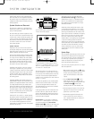
FRONT-PANEL CONTROLS
6 FRONT-PANEL CONTROLS
AVR 135 OM 12/3/04 12:11 PM Page 6