Chapter 1: Connections and Setup
Illustrations contained in this document are for representation only.
10
Wireless Voice Gateway
Wireless Voice GatewayWireless Voice Gateway
Wireless Voice Gateway
Overview
OverviewOverview
Overview
Front Panel
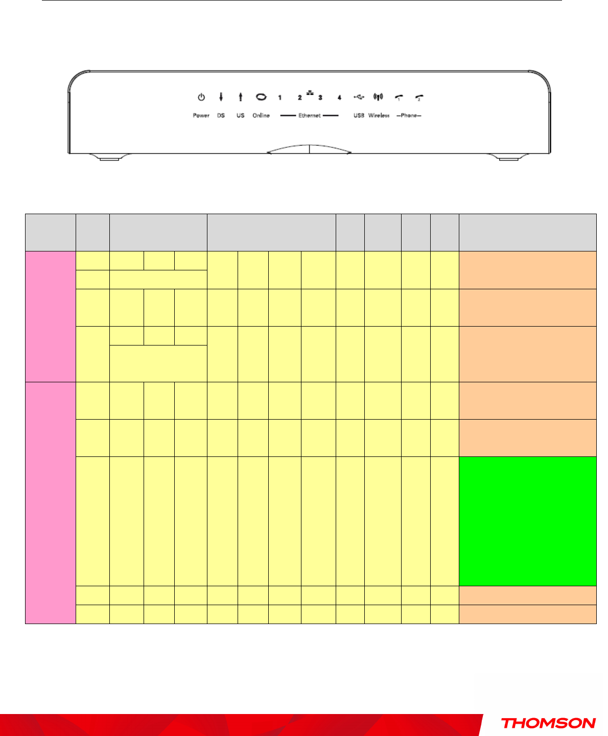
The following illustration shows the front panel of the Wireless Voice Gateway:
The LEDs on the front panel are described in the table below (from left to right):
Power
Internet
DS US Online
Ethernet
1 2 3 4
USB
Wireless
Tel 1
Tel 2
Description
Boot-up
Operation
ON ON ON
ON
ON ON ON ON ON
X ON
ON
Power on 0.25 sec
ON 0.25 second
ON FLASH
FLASH
FLASH
X X X X X X X X
From power ON to system
initialization complete
ON
ON ON
ON
X X X X X X X X
Following system initialization
complete to (before)
DS scanning
1 second
DOCSIS
Start-up
Operation
ON FLASH
OFF
OFF
X X X X X X X X
During DS scanning and acquiring
SYNC
ON ON FLASH
OFF
X X X X X X X X
From SYNC completed, receiving
UCD to ranging completed
ON ON ON
FLASH
X X X X X X X X
During DHCP, configuration file
download, registration, and
Baseline Privacy initialization:
DHCP status: 1 second ON and 1
second OFF,
TFTP status: 0.25 second ON and
0.25 second OFF
ON ON ON
ON X X X X X X X X Operational (NACO=ON)
ON FLASH
FLASH
OFF
X X X X X X X X Operational (NACO=OFF)


