


GB-7 [ENGLISH]
CONNECTING THE UNIT TO ANOTHER
DEVICE
- After the completion of all connections, adjust the image aspect ratio
for the TV (“4:3 LB”, “4:3 PS” and “16:9”) (See page 20).
- When connecting the unit to a progressive-mode-ready TV with NTSC
colour system capability, use the COMPONENT VIDEO OUT sockets.
It is possible to select the progressive mode (Auto/Video/Film) (See
page 20).
Cautions in making connections
- Before connecting the unit to another device, turn off the power
of the unit and disconnect the mains plug from the AC outlet.
- Connect the unit directly to a TV. If the unit is connected to a TV
through a VCR, images may be disturbed due to the copyright
protection function.
- Carefully read the instruction manual of the device to be connected.
- Before plugging and unplugging the mains lead of the unit, power off
the TV and devices connected to the unit. Failure to do so may
damage the speaker.
- To send out the video signal of a device being connected with the
VIDEO 1 IN “VIDEO” (or VIDEO 2 IN “VIDEO”) socket, the TV should
be connected to the VIDEO OUT or EURO AV CONNECTOR RGB
OUT/TV (AUDIO) IN socket. The video signal coming via the VIDEO
1 IN “VIDEO” (or VIDEO 2 IN “VIDEO”) socket will not be sent through
the S-VIDEO OUT or COMPONENT VIDEO OUT sockets.
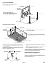
Connecting the unit to a TV
When connecting the unit to a TV having a VIDEO INPUT socket (Fig.
6)
If your TV has the VIDEO INPUT socket, connect the unit to the VIDEO
INPUT socket.
When connecting the unit to a TV having an EURO-AV socket (Fig. 7)
You can enjoy high quality picture playback. (Do not connect the video
lead to the VIDEO OUT socket.)
In this case, select “VIDEO OUT SELECT: RGB” (default) on “Changing
the display setting” setting (See page 20.)
When connecting the unit to a TV having an S-VIDEO INPUT socket
(Fig. 8)
You can enjoy clearer picture playback. (The VIDEO OUT socket connection
is not necessary.)
When connecting the unit to a TV having COMPONENT VIDEO INPUT
sockets (Fig. 9)
(Only for TV with NTSC colour system capability)
You can enjoy high quality picture playback. (The VIDEO OUT or S-
VIDEO OUT socket connection is not necessary.)
In this case, select “VIDEO OUT SELECT: COMPONENT” on “Changing
the display setting” setting (See page 20.)
An LCD video projector with NTSC colour system capability can also be
connected.
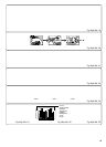
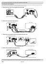
Example of another device connection (Fig. 10)
Connecting the analog audio output of another
device (Fig. 11)
Connecting the analog audio output of an audio equipment to the unit will
allow you to enjoy powerful sounds from the speakers of this unit.
Connecting the digital audio output of another
device (Fig. 12)
Connecting the digital audio output (optical/coaxial) of a MD deck or game
machine to this unit will allow you to enjoy 5.1- channel-ready sounds with
a surround-sound effect.
Note:
If the video signal of an external device is not to be inputted, it is possible
to input only the digital audio signal by changing the digital audio input
function mode (See page 25).
Connecting headphones
Connect stereo headphones (not supplied) to the PHONES socket for
monitoring or for private listening. The speakers are automatically
disconnected when headphones are connected.
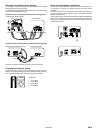
AERIAL/MAINS LEAD CONNECTIONS
Aerials (Fig. 13)
In areas close to a transmitter the simple indoor aerial is sufficient to
receive broadcasts. Extend the aerial wire as straight as possible and,
while listening to the sound from the system, secure it in a position which
yields minimal distortion and noise.
In fringe areas or where reception is distorted or noisy, an FM external
aerial (not supplied) should be connected instead of the simple indoor
aerial. Consult your dealer.
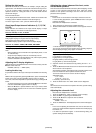
AM loop aerial
Assemble the loop aerial as shown in Fig. 14a. Unwind the aerial wires,
then connect the plug to the AM ANT. terminal. If you have difficulty
inserting the plug, turn it over and reinsert it. Place the loop aerial in a
position which yields the best AM reception, or attach it to a wall or other
surface as shown in Fig. 14b.
Note:
To minimize noise, the speaker, mains and any other leads should not
come close to the indoor or external aerial lead and AM loop aerial. Do not
place the aerial leads close to the system.
Mains supply
(Main unit, Front speaker with mains lead and Surround speaker with
mains lead)
After all connections have been made, connect the mains lead to an AC
outlet.
Note:
Do not connect the mains lead to an AC outlet until all connections have
been made.
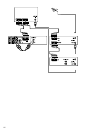
SYSTEM CONNECTIONS EXAMPLES
JCX-TS960, TV and Audio equipment (Fig. 15)
JCX-TS960, TV and VCR (Fig. 16)
JCX-TS960, TV, VCR and Audio equipment (Fig. 17)
JCX-TS960, TV, VCR, STB (Set Top Box) and Audio equipment (Fig.
18)