


11
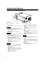
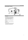
Controls and Features
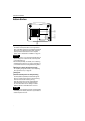
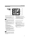
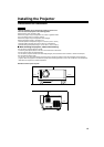
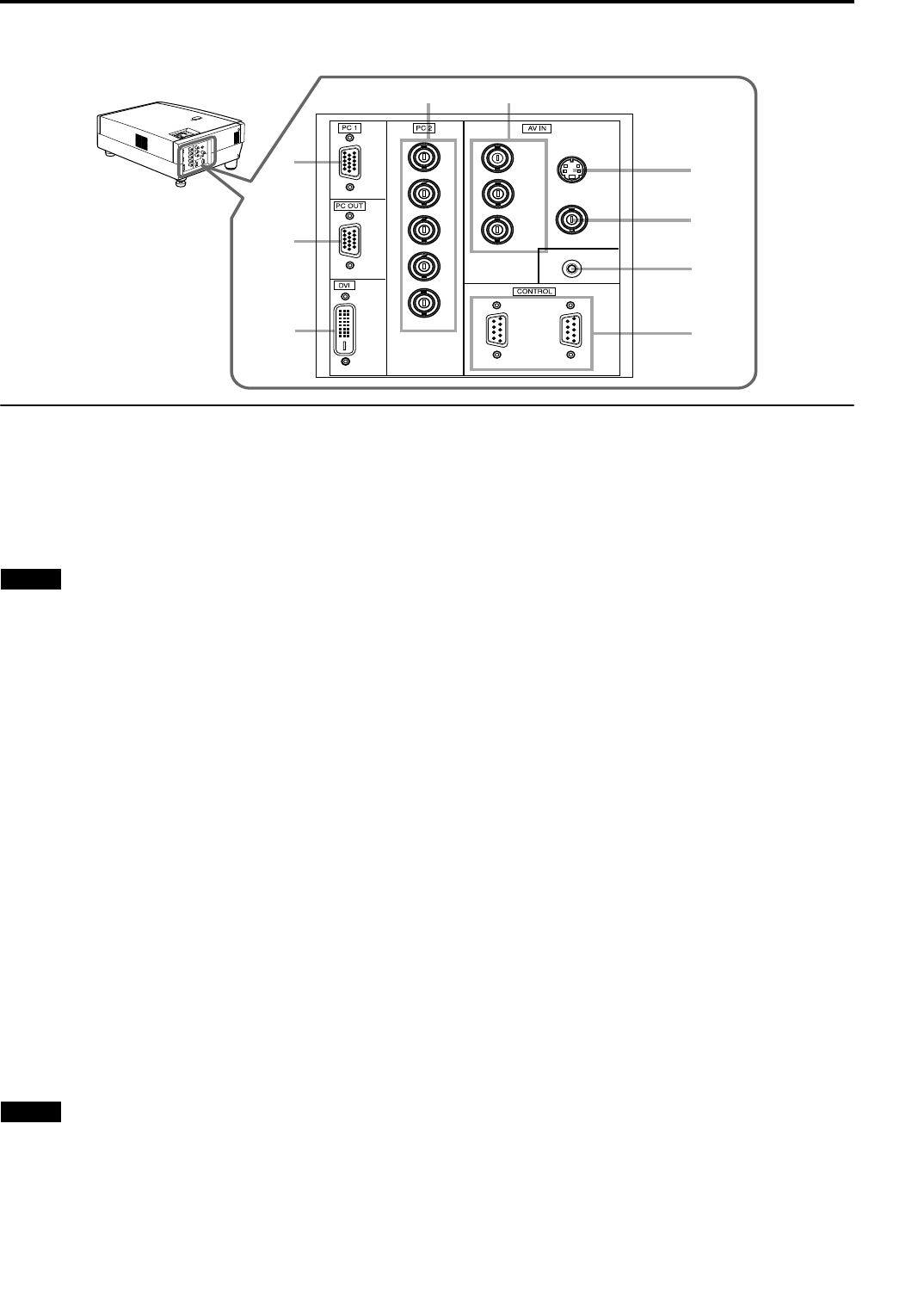
Connector Panel
1 PC (computer) 1 input terminal (D-sub 3-row 15
pin)
This is an input terminal dedicated to computer signals
(RGB video signals and sync signals).
Connect the display output terminal of the computer to
this terminal. When a Macintosh computer is to be
connected, use the supplied conversion adapter for Mac.
Note
•When computer-related signals are input, the uppermost
edge of the image may appear to bow if the sync signal
input is composite sync (Cs) or G on sync signal. In this
case, use separate sync signals for vertical sync (V) and
horizontal sync (H).
2 PC (computer) OUT terminal (D-sub 3-row 15 pin)
This is the terminal for video output from the monitor of
the computer connected to PC1 or PC2.
The computer input signal projected on the screen is
output. A display monitor can be used by connecting it to
this terminal.
3 DVI terminal [DVI-D 24 pin]
This is the digital RGBHV input terminal.
• Connect Video Processor here.
4 PC (computer) 2 input terminals (BNC ×
××
×
5)
These are multipurpose video input terminals that allow
input of the following signals.
•Analog RGB signals, vertical sync (V) signals, and
horizontal sync (H) signals / composite signals (Cs).
(Devices which have analog RGB signal output
terminals can be connected.)
* Input of external sync signals is automatically detected.
Detection of H/V signals or Cs signals causes automatic
switching to external sync. The priority order is H/V > Cs.
Note
•When computer-related signals are input, the uppermost
edge of the image may appear to bow if the sync signal
input is composite sync (Cs) or G on sync signal. In this
case, use separate sync signals for vertical sync (V) and
horizontal sync (H).
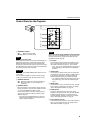
5 Component terminal
Component signals (Y, B-Y, R-Y) or DTV-format (Y, PB,
P
R) signals. (Devices which have component output
terminals can be connected.)
* Connect 480i/480p Component sources to Video Processor,
YPrPb HDTV sources can connect directly here.
6 Y/C (S-video) input terminal (Mini DIN 4 pin)
Connect S-video sources to the Video Processor.
7
VIDEO (composite video) input terminal (BNC)
Connect Video to the Video Processor.
8 REMOTE terminal (stereo mini jack)
Connect an infrared remote control extension unit, etc. to
this jack.
Attach the ferrite core (accessory) to the cable which is
connected to the REMOTE terminal. (Refer to page 29.)
* For details, consult your dealer.
9 RS-232C CONTROL terminal IN/OUT (D-sub 9 pin)
This is the RS-232C interface-specified terminal. The
projector can be controlled by a computer connected
externally.
*For details, refer to page 27 and 74.
2
3
1
54
7
8
9
6
V
I
D
E
O
P
C
L
A
M
P
T
E
M
P
S
T
A
N
D
B
Y
M
E
N
U
K
E
Y
S
T
O
N
E
P
R
E
S
E
T
E
X
I
T
E
N
T
E
R
O
P
E
R
AT
E
H
I
D
E
D
O
W
N
UP
Y
P
B
/B-Y
P
R
/R-Y
IN
REMOTE
Y/C
VIDEO
R
G
B
H
IN OUT
V