


Quad Amp Hardware Reference Manual
Troubleshooting 31
In the case of multiple axis-specific faults on one axis, the higher-numbered fault shall be indicated.
In the case of axis-specific faults on multiple axes, the axis with the higher-numbered fault shall be
displayed along with the decimal point indicting its axis number.
In the case of axis-specific faults of the same number on multiple axes, the fault number shall be
displayed and decimal point indication shall specify the higher-numbered axis.
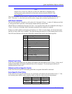
Problem Check Corrective Action
Under voltage
indicator comes on
when power is applied.
This is a normal condition. When AC power is first applied, the Soft Start
has not been initialized and the bus is not
charged. This results in a low line fault. The
first enable command (usually o0) will initialize
the Soft Start. The following CNTL K command
will ensure that no motor is enabled. It will also
turn the Soft Start IGBT on and allow the bus cap
to charge.
Quad Amplifier
enables normally but
LED Fault Indicator
displays C after a
motor is moved.
Check if the bus voltage holds steady
after an axis is enabled and/or moved
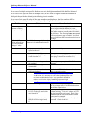
Motor does not turn. 1. Is the correct main AC power
applied to the unit?
Apply correct AC power.
2. Is a motor connected? Connect motor.
3. Is the power enable (E-Stop)
switch closed at C1?
Close E-Stop switch. (If E-Stop not used, make
sure a plug is installed on connector C1.)
4. Is PMAC2 connected, powered
and working?
Connect, power up or replace PMAC2 if
necessary.
5. Is the correct axis being
commanded?
Command the correct axis.
6. Is there a fault indicated on the
LED Fault Indicator?
Refer to the LED Fault Indicator fault codes and
take the corrective action.
Warning:
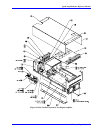
At this point, it is necessary to remove the Quad Amplifier cover
to further troubleshoot the unit. Every precaution should be
taken to avoid serious injury from being exposed to high
voltages.
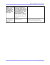
7. Is there a bus voltage? Make sure the AC power is applied and check for
DC bus voltage across 15 k Ohm bleed resistor
on the filter capacitor box.
8. Are all logic supply LEDs (D5,
D6, D7) on the logic and current
sense boards lit?
An unlit power supply LED means that a supply
is bad or missing. Check AC voltages at J5 of
the Quad Amplifier logic board. Check if the
cable between the logic board and the current
sense board is connected.
9. Is the commanded axis enable
LED (D18-D21 on logic board)
lit?
Generally, enable LED comes on after #xo0
command. Check if Ix00 is 1.