


Quad Amp Hardware Reference Manual
Installation 15
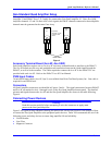
INSTALLATION
Wiring the Quad Amplifier System
Quad Amplifier Channel Connections
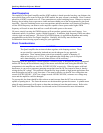
The Quad Amplifier channels must be connected in a particular order for proper operation. It is essential
that the timing of all signals associated with the Quad Amplifier logic board shares the ADC converter
clocks for Quad v channels 1-2 and channels 3-4. The ADC clocks are generated from the gate array
associated with the axis channel on the PMAC. Each PMAC Gate Array controls four axis channels.
Therefore, make sure to connect Quad Amplifier channels 1 and 2 or channels 3 and 4 to the same PMAC
channels associated with the same ADC clock Gate array. Faulty operation or even amplifier failure may
occur if the user mixes Gate Array channels on either Quad Amplifier channels 1-2 or 3-4. The following
chart lists the possible combinations for proper Quad Amplifier operation.
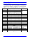
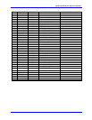
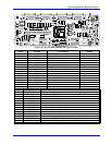
Two Quad Amplifier Example
PMAC Axes Quad AMP 1
Channels 1-2
Quad AMP 1
Channels 3-4
Quad AMP 2
Channels 1-2
Quad AMP 2
Channels 3-4
Configuration 1 A A B B
Configuration 2 A B A B
Configuration 3 A B B A
Configuration 4 B A B A
Configuration 5 B A A B
Configuration 6 B B A A
(A) Can have the following PMAC Axis configuration (GATE 0)
1-2 or 3-4
1-3 or 2-4
1-4 or 2-3
(B) Can have the following PMAC Axis configuration (GATE 1)
5-6 or 7-8
5-7 or 6-8
5-8 or 6-7
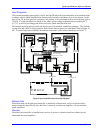
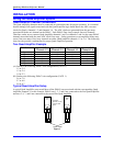
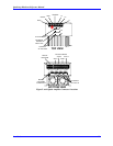
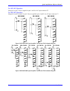
Typical Quad Amplifier Setup
A typical Quad Amplifier setup would have all the PMAC axes associated with the corresponding Quad
Amplifier channels. For this example, PMAC axes 1, 2, 3 and 4 are connected to the first Quad Amplifier
and axes 5, 6, 7, and 8 are connected to the second first Quad Amplifier.
3 4
1 2
1 3 4 2
QUAD
AMP
#1
1 3 4 2
QUAD
AMP
#2
7 8
5 6
PMAC AXES
* Quad Amp
channels 1-2 and
3-4 share ADC
clocks
Figure 3