


Quad Amp Hardware Reference Manual
Installation 21
Bus Power Enable/Emergency Stop
CAUTION:
Any wiring should be attempted only after the drive has been isolated from the main
AC supply and 10 to 12 minutes has elapsed to allow the internal bus capacitors to
discharge.
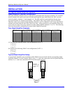
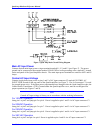
The normally open (NO) Main AC Contactor auxiliary contacts must be wired and connected to Connector
C1 pins 1 and 2, otherwise the Quad Amplifier will not power up. Connector C1 is located on the top of the
Quad Amplifier (See Figure 9)
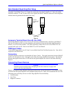
Shunt and Bus
Resistor terminals are provided so that the user can connect an external shunt resistor to the Quad Amplifier
(See Figure 10). The shunt resistors should be a resistive (non-inductive) load of appropriate power and
voltage rating for the bus and the regenerative load. External shunt resistors are available from Delta Tau as
Quad Amplifier Acc-4. These resistors (two 4.25 ohm, 1400W resistors for 230 VAC operation and three
4.25 ohm, 1400W resistors for 380/460 VAC operation), when connected in series (8.5 ohms total), will
dump over 45 amps.
Bus
Along with the BUS- terminal, these terminals may be used to power external servo amplifiers. Consult
Delta Tau Data Systems Technical Assistance for information concerning external servo amplifiers. .
Bus Filter/Indicator
The bus filter/indicator board is mounted to the Bus+ and Bus- power bars, which are located between Axis
1 and 3 and Axis 2 and 4 output blocks inside of the Quad Amplifier. The bus filter/indicator board is
equipped with a neon light that illuminates when bus voltage is present. If the Main AC Power is turned
off, the neon light will stay lit until the bus voltage discharges to about 80 VDC.
Motor Wiring
The motor cable wire gauge for each axis must be sized to handle the continuous output current of the axis
to which it is connected.
Motor Over-Temp Sensor
The output pins of the 9-pin DIN connector, located on the end panel of the Quad Amplifier, must be
connected to the motor over-temp switches. If this connector is not connected to the motor over-temp
switches, it must be jumpered with a Delta Tau supplied termination connector for normal Quad Amplifier
operation.
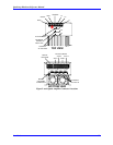
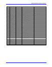
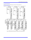
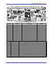
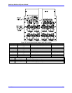
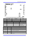
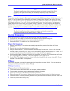
Jumpers, Potentiometers, Test Points, and LEDs
There are configurable jumpers, potentiometers, test points, and LEDs on the circuit boards inside the Quad
Amplifier. The jumpers are factory set to each customer’s specifications and usually do not need to be
changed. Figures 10 through 12 show the locations of these jumpers, potentiometers, test points, and LEDs.
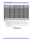
The following tables list the default jumper settings, the Soft Start board potentiometer factory settings and
test point voltages, describe the LED indications for each board.