


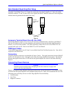

Quad Amp Hardware Reference Manual
Installation
2
4
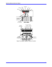
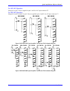
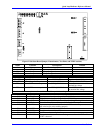
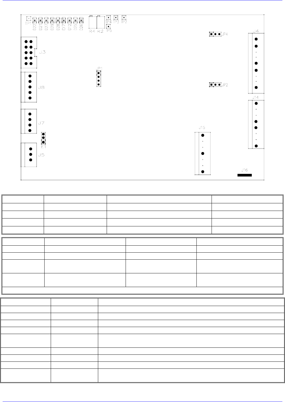
Figure 62 Soft Start Board Jumper, Potentiometer, Test Point, and LED Locations
Name Position Description Default
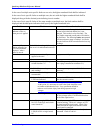
E1 1-2 jumper Internal Power Supply Connection
2-3 open
JP6 Jumper E-Stop Configuration
JP7 Jumper E-Stop Configuration
Symbol` Description Tp Factory Set Notes
R4 & TP5 High line fault set point 5.2/10.4 V High line trips at 255/510 VAC
R2 & TP4 Over voltage fault set point 4.1/8.2 V O/V trips at 410/820 VDC
TP3 Shunt IGBT turn-on set point 3.7V @ 230 VAC Shunt turns on at 114% of the
nominal bus voltage
TP2 Main IGBT turn-on set point 2.75V @ 230VAC Main IGBT turns on at 80% of
the nominal bus voltage
Note: Main and shunt set points are line sensitive and will vary with line voltage.
LED Symbol Description
D25 L/LOW Low Line, on when line voltage is below 30 VAC
D12 L/HI High Line, on when line voltage is above 255 VAC
D7 GND GND Fault, on if GND fault detected by Quad Amplifier logic board
D29 BIAS Gate drive/bias fault, on if the gate drive supply fails
D27 OPEN Open contacts fault, on when no main AC contactor auxiliary contacts are
not wired to QA or not working properly
D21 SHNT Shunt, on when the shunt regulator is on
D22 RDY Ready, on when no fault condition
D26 NOLINE No Line, on when no 3-phase line present
D28 DSAT De-saturation fault, on when current surge across the main IGBT or Shunt
IGBT is detected