


Quad Amp Hardware Reference Manual
Installation 19
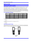
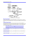
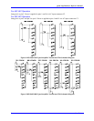
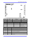
Figure 7 Quad Amp Main Circuit Wiring Diagram
Main AC Input Power
Connect desired main input power to input terminals marked L1, L2, and L3 (see Figure 7). The power
ground can be connected at the terminal marked CHAS GND or at the grounding screw, marked E, located
on the end panel of the Quad Amplifier chassis. The main input power terminals are rated for 600V and 85
Amps.
Control AC Input Voltage
Connect single-phase input power to pins 1 and 2 of AC input connector C3 marked CONTROL AC
INPUT PWR, located on the top panel of the Quad Amplifier (see Figure 7). Pin 4 of connector C3 is used
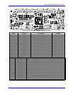
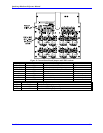
for ground (green wire). If the input power requirements have changed since the Quad Amplifier order, the
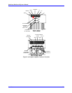
Control Power Transformer (T201), located under the Quad Amplifier cover, must be reconfigured for
proper operation (see Figures 7 and 8).
Note:
Control AC Input voltage is factory set in accordance with the ordering information.
For 120VAC Operation
Jump pin 1 to pin 5 and jump pin 2 to pin 6. Power is applied to pins 1 and 2 via AC input connector C3.
For 208VAC Operation
Jump pin 1 to pin 5 and jump pin 3 to pin 7. Power is applied to pins 1 and 3 via AC input connector C3.
For 230VAC Operation
Jump pin 1 to pin 5 and jump pin 4 to pin 8. Power is applied to pins 1 and 4 via AC input connector C3.
For 380 VAC Operation
Jump pin 4 to pin 5 and pin 6 to pin 9. Power is applied to pins 1 and 10 via AC input connector C3.