


Quad Amp Hardware Reference Manual
Installation
22
123
3
21
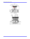
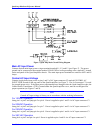
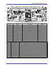
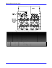
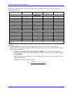
Figure 10 Logic I/O Board Jumper and LED Locations
Name Position Description Default
E1-E4 IN Shield To Local Ground Open
OUT
E7 IN Do Not Use Open
OUT
E8 IN Enable Shunt Transistor In Module Open
OUT
E9 IN Enable Shunt Transistor In Module Open
OUT
E10 IN Do Not Use Open
OUT
E28 IN Do Not Use Open
OUT
E29 IN Do Not Use Open
OUT
E30 IN Do Not Use Open
OUT
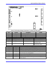
LED Symbol Description
D5 + 15 V On when + 15VDC logic power is present
D6 + 5 V On when + 5 VDC logic power is present
D7 - 15 V On when - 15 VDC logic power is present
D14 AXIS 1 FLT On when Axis #1 faulted
D15 AXIS 2 FLT On when Axis #2 faulted
D16 AXIS 3 FLT On when Axis #3 faulted
D17 AXIS 4 FLT On when Axis #4 faulted
D18 AXIS 1 EN On when Axis #1 is enabled
D19 AXIS 2 EN On when Axis #2 is enabled
D20 AXIS 3 EN On when Axis #3 is enabled
D21 AXIS 4 EN On when Axis #4 is enabled
D22 PWR GOOD On when all logic powers are at the proper level
D50 GOT ENABLE On when any AXIS ENABLE signal is received at the Logic PCB
D55 VNI On when + 15 VDC logic power for output IGBTs is present