


Quad Amp Hardware Reference Manual
Installation
1
6
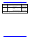
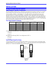
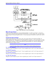
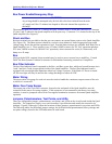
Non-Standard Quad Amplifier Setup
This example shows the Quad Amplifier setup with PMAC axes 1, 2, 7, and 8 are connected to first Quad
Amplifier #1 and PMAC Axes 3, 4, 5 and 6 are connected to first Quad Amplifier #2. Since first Quad
Amplifier channels 1-2 and 3-4 share ADC clock signals, the PMAC channels connected to these amplifier
channels must be generated at the same Gate Array.
7 8
1 2
1 3 4 2
QUAD
AMP
#1
1 3 4 2
QUAD
AMP
#2
3 4
5 6
PMAC AXES
* Quad Amp
channels 1-2 and
3-4 share ADC
clocks
Figure 4
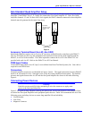
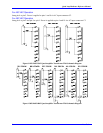
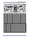
Accessory Terminal Board (Acc-8F, Acc-24E2)
Each Quad Amplifier requires one or two Acc-8F accessory terminal boards to interface to the PMAC2.
The Acc-8F boards provide easy and straightforward connections between the Quad Amplifier and the
PMAC2, as well as to the encoders. The cables required to connect the Acc-8F to the PMAC2 PC are
provided with each Acc-8F. Refer to the PMAC2 Acc-8F User Manual.
PWM Input Cables
36-inch PWM input cables (Acc-8F, Opt 5) are available from Delta Tau Data Systems, Inc. One cable is
required for each PWM axis.
Connectors
All Quad Amplifier connectors are identified in Figures 5 and 6 . The signal connections between PMAC2
and Acc-8F are marked as Axis 1 through Axis 4 on the first Quad Amplifier bottom panel. The detailed
pin-outs and signals between the Acc-8F and the first Quad Amplifier are shown in the table following
Figure 6.
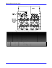
Connecting Power Devices
Warning:
Read this section carefully before attempting to wire the connectors or apply main
power to the first Quad Amplifier.
Figure 5 is a typical wiring schematic showing the main power circuits and Figure 6 is an example of how
to connect the first Quad Amplifier to the peripheral power devices. Delta Tau recommends the use of the
following power and safety devices to ensure long amplifier life and reliability.
• Circuit Breaker
• Line Filter
• Magnetic Contactor