


Quad Amp Hardware Reference Manual
Theory of Operation
12
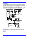
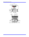
Current Sense Board
The Current Sense Board has eight Hall Effect (LEM) modules for current sense and eight on-board A/D
converters that transform four channels of motor current to digital form. Each channel provides
information on two phases (A phase and B phase). The third phase is mathematically created in the
PMAC2.
Firing Boards
The firing boards receive their signals directly from the PMAC2 through the Logic board differential
receivers and turn appropriate top and bottom IGBT on to allow current flow through a motor phase
(winding). The PWM signals are opto-isolated before they reach the IGBT firing pins. The firing pulses
for each IGBT transistor are differential to increase noise immunity. To avoid ground loops and
accidental IGBT turn-on, each firing board is equipped with an isolated power supply.
Soft Start and Shunt Regulator
The Soft Start and Shunt Regulator circuit board’s function is to provide soft charge and shunt regulation
for the Quad Amplifier. It consists of a main board (602800-1) and a dual split gate drive power supply
piggy board (602801-1) that mounts on the main board with plastic screws and standoffs.
The Soft Start and Shunt Regulator Main and Shunt set points (when main IGBT and shunt IGBT turn on)
are set as a percentage of the nominal bus voltage for the actual AC line voltage. Therefore, set points
move automatically with the line voltage. This allows operation at any line voltage above 30 VAC and
prevents shunt damage under high line conditions. A condition above 250/500 VAC will cause a high
line fault, which will prevent operation of the Quad Amplifier. Over voltage is set at 410/820 VDC and
can be factory set lower with R2.
If there is an absence of logic power (+/- 15V), the split gate drive power supply will not be able to power
the K1 relay and bus voltage is prevented from coming up because the main and soft start IGBT gates and
emitters are shorted via the K1 relay (NC) contacts.
Soft Start
If there is no 3-phase line voltage (VAC) present, a No Line fault condition prevents momentary main
operation on power-up before line sense levels are up. Once 3-phase line voltage is applied, the No Line
fault is cleared by a clear fault pulse, which comes from Quad Amplifier logic board upon issuing an
Enable command. When Enable is issued, the Soft Start IGBT will turn on and charge the bus capacitors
via Soft Start resistor (100 Ohm, 50 Watts). After the bus capacitors are charged to 80% of the nominal
bus voltage for the AC line, the main IGBT will turn on, bypassing the Soft Start resistor.
Shunt Regulator
When the bus voltage rises to 114 % of the nominal bus voltage for the AC line due to a deceleration of a
motor, the shunt IGBT turns on and connects the shunt resistor across the bus until the bus voltage drops
to normal. The value of 114% was selected so that even at 250 VAC (about 353 VDC bus) the shunt
regulator will turn on at approximately 400 VDC before the over voltage (410VDC) trips.
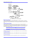
DC Bus Power Supply
The AC Input voltage from L1, L2, and L3 is rectified into a DC bus voltage. The DC Bus Power Supply
consists of a three-phase rectifier bridge and an IGBT switch. The 208/230 VAC amplifier has a 15 k
Ohm bleeding resistor and six 1,800 µF filter capacitors, connected in parallel. The 380/460V Quad
Amplifier utilizes a serial/parallel configuration of six filter capacitors and two 15 k Ohm bleeder
resistors in series across + Bus and – Bus.