


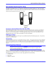

Quad Amp Hardware Reference Manual
Theory of Operation 11
THEORY OF OPERATION
Operation
The Quad Amplifier is a universal 4-axis 3-phase direct PWM drive which utilizes the latest in smart
power technology from the world’s leading vendors and the cutting edge algorithms of the new PMAC2
controller family. The Quad Amplifier is capable of driving all of the motor types commonly used in
programmable motion control in both rotary and linear forms.
The Quad Amplifier is based on PWM (Pulse Width Modulation) which is a technique employing both
frequency and phase to approximate sinusoidal currents and to control AC and DC motors.
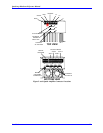
Each axis of the Quad Amplifier uses a three H-bridge legs scheme. Each leg employs top and bottom
IGBT transistor. The motor windings are connected between the center points of top and bottom pairs.
When two appropriate IGBT transistors in the bridge are turned on, the current flows through any two
motor windings. Any two (top and bottom) bridge transistors are turned on by a logic from PMAC2 with
no other conditioning necessary, except an optical isolation. The Quad Amplifier performs no control
functions itself; it simply accepts direct PWM commands from the PMAC2. PMAC2 requires the
position feedback and the feedback about the current fed to the motors to commutate each controlled axis.
The current feedback is provided in digital form as a part of a serial data stream of 18-bits (12 bits report
the current feedback and remaining 6-bits report fault conditions) from the current feedback A/D
converters which are located in the Quad Amplifier. Each axis has its own mask word that tells the
PMAC2 how many bits to expect from the A/D converter. The clock and the strobe for the digital
feedback are programmable at the PMAC2.
The position feedback in the form of quadrature A, B and C and/or ChU, ChV, ChW and ChT generally is
fed to PMAC2 via Acc-8F. The position feedback is not connected to the Quad Amplifier in any way.
Configuration
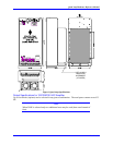
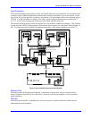
The Quad Amplifier consists of the following:
• One main logic board (I/O)
• One 4-axis current sense board
• One firing board for each IGBT power device. One for each axis, four axes maximum.
• One soft start and shunt regulator board
• One DC bus power supply
Logic Board
The Logic Board (I/O) acts as link to PMAC2 (via Acc-8F) and has several functions (All signals
arrive/and leave the logic board through a separate mini DB36 connector for each axis):
1. Differential PWM signals are opto-isolated and sent directly to the firing boards.
2. All the control signals for the current sense board are transmitted to the current sense board via a flat
60-pin cable. The digitized current feedback is routed back from the current sense board via the same
cable and is passed to PMAC2 through a mini-D36 connector.
3. The Logic Board processes Amp Enable and Amp Fault signals for all four axes. The Amp Enable is
a differential pair and a separate line is supplied from PMAC2 for each axis. The default polarity of
Amp Enable is positive true. A high on AENA+ and a low on AENA- will enable the Quad
Amplifier. In the event of a failure, the Quad Amplifier will drive the Amp Fault line positive true
and send the fault signal to PMAC2.
4. It provides protection against various Quad Amplifier fault conditions and it displays a condition of
the Quad Amplifier via an LED Fault Indicator on the Current Sense board (see Fault Detection and
Fault Codes section in this manual).