


SC3100
System Initialization
SC3100 Operation and Installation Guide
© 2004 Bosch Security Systems Page 25 90026-201D
red. The number of blinks indicates a specific type of hardware failure. The blinking cycle will continue until
the auxiliary power source is removed from the SC3100.
The following describes the red blinking behavior of the System Status LED during a hardware failure, and
should not be confused with System Status green LED illumination during normal SC3100 operations:
• 1 blink red, pause, then repeat: Bad ROM check sum.
• 2 blinks red, pause, then repeat: Failed RAM verify test.
• 3 blinks red, pause, then repeat: Invalid CPU serial number.
• 5 blinks red, pause, then repeat: The SC3100 internal battery is low and must be charged.
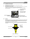
5.3 Manual Initialization of an SC3100 Radio Communicator
The SC3100 Radio Communicator may be manually reset/initialized. The reset/initialize function is performed by
a sequence involving momentarily shorting pins #1 and #2 on the JP-1 CPU RST Header. The JP-1 Header is
located on the main SC3100 circuit board and requires disassembly of the SC3100 Radio Communicator.
Note: A manual initialization should only be performed if all efforts to initialize the SC3100 via a radio command from
the SAFECOM SC9000 Computer have failed. Manual initialization must be performed at the customer site and
requires removing the SC3100 panel cover and battery plate.
The following procedure will erase all the programmed data in the CPU with the exception of the CPU serial
number.
To manually initialize the SC3100 Radio Communicator:
1. Remove the auxiliary power source from the SC3100. Power Off.
2. Loosen the 4 retaining screws on the SC3100 panel cover and remove the cover.
3. Loosen and remove the screws and battery mounting shelf, exposing the main SC3100 circuit board.
4. Short the 2 pins on the JP-1 Header together. Keep the short in place.
5. Apply the auxiliary power DC power source to the SC3100. Power On. This step will Initialize the CPU. The
System Status LED will blink red three (3) times, pause, then repeat. This indicates that all of the Parameter
EEPROM Memory, in the CPU, has been erased.
6. Remove the short between the 2 pins on the JP-1 Header.
7. Remove the auxiliary power from the SC3100. Power Off.
8. Replace the SC3100 battery mounting shelf, panel cover and tighten four retaining screws.
Apply auxiliary power to the SC3100. Power On. This step will initiate a system startup. The SC3100 will behave
exactly like a brand new unit.