


SC3100
Pre-Installation Requirements
SC3100 Operation and Installation Guide
© 2004 Bosch Security Systems Page 15 90026-201D
3.0 Pre-Installation Requirements
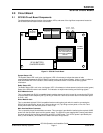
3.1 SC3100 Pre-Installation Requirements
Prior to the installation of the SC3100 Radio Communicator, several conditions must be satisfied and physical
phenomena considered to insure trouble free operation.
3.2 SC3100 Wiring Requirements
All wiring utilized for the installation of the host alarm panel and the SC3100 Radio Communicator shall be in
accordance with local building codes. The following is recommended gauge and type wiring for installation of the
host alarm panel and the SC3100:
• Alarm panel dialer phone lines: in accordance with industry installation standards.
• SAFECOM antenna RF cable: It is always preferred to utilize the RF cable provided by Bosch Security
Systems for installations of SC3100 Radio Communicators.
• SAFECOM antenna RF cable for remote antenna installation: The antenna should be located remotely away
from the SC3100. For distances of 15 ft. (4.6 m) or less, use RG-58 or equivalent. For distances up to 30 ft.
(9.1 m), use RG-8 or equivalent. For distances exceeding 30 ft. (9.1 m), contact a Bosch Security Systems
SAFECOM Applications Engineer for recommendations.
• 12 VDC power from host alarm panel auxiliary power: Minimum 20 AWG (distance dependent).
3.3 DC Power Requirements of the SC3100 Radio Communicator
The SC3100 requires an 11-15 VDC (12 VDC), 350 mA, power source capable of providing 850 mA during
transmission if the internal battery is not used. The 12 VDC power source supplies the operating voltage
requirements for the SC3100 circuit board and charging the internal SC3100 battery. This 12 VDC power source
is normally provided by the auxiliary power terminal of the host alarm panel. However, an 11-15 VDC stand alone
DC power supply or external battery is an acceptable power source for the SC3100.
The SC3100 should not be connected to the battery terminal or smoke detector power of the host
alarm panel.
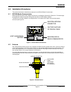
3.4 SC3100 Internal Battery
The SC3100 is provided with a 12VDC battery. This battery provides all of the necessary peak current (amperes)
requirements for the SAFECOM Radio Transceiver. This battery is mounted inside of the SC3100 Radio
Communicator and is accessible by removing the enclosure cover. Primary 12 VDC operating power for the
SC3100 is normally supplied by the host alarm panel.
Note: The SC3100 internal battery might not be at full capacity after an idle no-charge period during shipping from
Bosch Security Systems. The SC3100 battery must be connected internally and charged for a minimum of 3
hours prior to initialization for radio communications. This will ensure that the SC3100 internal battery charge is
a minimum 11.5V DC when the SC3100 is initially powered up for operation.
3.4.1 SC3100 Internal Battery Replacement
The SC3100 is provided with an internal 12VDC, 0.8 AHr, sealed gel cell battery. A replacement battery may be
purchased from Bosch Security Systems, (800) 289-0096.
3.4.2 Replacing the SC3100 Battery
1. Remove the external 12 VDC power source from the host alarm panel.
2. Loosen the four retaining screws on the SC3100 main enclosure cover.
3. Locate and remove the battery from the battery plate.
4. Disconnect the battery two pin Molex connector between the battery and the SP100 Battery Charger Board.
5. Connect the two pin Molex connector to the new battery.
6. Reverse the above procedures to install the new battery and replace the SC3100 enclosure cover.
7. Re-connect the host alarm panel auxiliary 12 VDC power source.