


SC3100
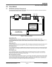
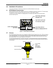
SC3100 Circuit Board
SC3100 Operation and Installation Guide
© 2004 Bosch Security Systems Page 13 90026-201D
The battery restore message will NOT be sent by the SC3100 until the charge on the SC3100 Battery has
reached a minimum of 11.5 VDC during transmit TX ACTIVE.
Note: The SC3100 battery voltage is only tested when the radio transceiver is transmitting.
Note: The SC3100 internal battery is shipped from Bosch Security Systems disconnected. The installer MUST open
the SC3100 enclosure and connect the internal battery connector. It is then recommended that the SC3100 be
programmed into the SC9000 computer and brought ONLINE for a minimum of 3 hours prior to installation to
charge the internal battery to a sufficient level. The SC3100 internal battery may NOT be charged to full capacity
after an idle, no-charge period, such as during shipping from Bosch Security Systems.
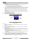
2.3 Radio Status LED Indications
The Radio Status LED illuminates to indicate the current transmit and receive status of the SC3100 Radio
Communicator. This is a bi-color (red & green) LED. It illuminates to indicate the current transmit (red) and
receive (green) status of the SC3100 internal radio module. This indication is helpful when sending and receiving
signals.
This LED will illuminate red when the SC3100 is Transmitting a signal to the Central Station.
This LED will illuminate green when the SC3100 is receiving any radio signals (Carrier Detect - CD) on the Radio
Receiver frequency. This green indication can mean the SC3100 is receiving a signal from the Central Station, is
hearing another SAFECOM Radio Communicator in the field, is being interfered with due to a high level of RF
noise in the area, or is being intentionally jammed on the RX frequency.