


SC3100
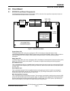
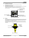
SC3100 Circuit Board
SC3100 Operation and Installation Guide
90026-201D Page 12 © 2004 Bosch Security Systems
JP1 - CPU Reset (Reboot)
This allows system reset or initialization of the Central Processor Unit (CPU). Shorting the two pins on this
header and cycling the system power will erase the program from the SC3100, making it operate as if it was a
“new, out of the box” unit.
Radio
This header is to connect the interface cable from the internal RA500 Radio Module to the radio adapter board
inside the SC3100.
JP-3-SP100 Charger Header
This four-pin header is used to interface the main SC3100 board to the SP100 Battery Charger board. The
SP100 is mounted “piggy-back” on this header, and is secured in place with a single ¼-inch standoff.
Note: To operate the SC3100 without the supplied internal battery, remove the SP100 Battery Charger Board and
battery, and place a jumper across the two pins closest to the CPU on Header XX. This requires a stable well-
regulated power source for operation without the internal battery.
Battery Cut-Off Relay
This relay disconnects the internal 12VDC battery from the SC3100 circuitry when the external DC power source
is removed.
Note: Once the SC3100 is programmed and brought on-line, this relay is disabled.
R42 - TX Dev Adj
This is the adjustment for the Radio Transmitter Modulation Deviation set by Bosch Security Systems at the
factory. Do not make field adjustments.
Do not make field adjustments. Field adjustments of the Radio Transmitter Deviation made by unauthorized
personnel may violate FCC regulations.
U1 - Microprocessor
This contains the system program the SC3100 needs to operate. This program is downloaded into the
microprocessor from the SAFECOM computer via the SAFECOM radio network when the SC3100 is first
powered up. The label on the microprocessor specifies the CPU S/N and PID # of this particular SC3100.
U3 - Modem Chip
This is the SC3100 Modem used for converting the Serial Data stream from the SC3100 main board to an audio
signal that can be transmitted via the SAFECOM radio network.
2.2 System Status LED Indications
The System Status LED lights up to indicate the status of radio communications between the SC3100 and the
Central Station SC9000 computer. It also can indicate a low internal battery condition. The System Status LED
also functions as a hardware fault indicator.
There are 5 types of System LED indications for various conditions of a properly programmed SC3100 in the
field:
• Rapid blinking green: The System LED blinks green continuously at a rate of 5 times per second. After 90
seconds of power-up, this LED indicates that the SC3100 is in radio communication with the Central Station
SC9000 computer and is online. This LED also indicates that the charge on the SC3100 internal battery is
Good (~ 11.5-14 VDC). Communications = Good, Battery = Good
• Rapid blinking red: The System LED blinks red continuously at a rate of 5 times per second. After 90
seconds of power-up, this LED indicates that the SC3100 is not in radio communication with the Central
Station SC9000 computer and is offline. This LED also indicates that the charge on the SC3100 internal
battery is good (~ 11.5-14 VDC). Communications = Bad, Battery = Good
• Slow blinking red: The System LED blinks red slowly 5 times, then pauses for one second, then returns to
the 5 slow red blinks. This LED indicates that the SC3100 system has shut down because the charge on the
SC3100 internal battery is so low that it cannot activate the radio transmitter to send a message.
Communications = Bad, Battery = Bad
The SC3100 will attempt to re-establish communications with the Central Station every 15 minutes after the low
battery shutdown condition occurs. If the charge on the SC3100 Battery has not reached a minimum of 11.5
VDC, then the SC3100 will remain in the shutdown condition for another 15 minute period. It will continue this
attempt then shutdown cycle until the battery charge has reached the minimum level.