


SC3100
System Initialization
SC3100 Operation and Installation Guide
90026-201D Page 24 © 2004 Bosch Security Systems
30= Long 2300 Hz ACK Tone, Any digital pulse type format.
31= Long 2300 Hz ACK Tone, Radionics BFSK.
32= Long 2300 Hz ACK Tone, 0-2 pulse type format.
33= Long 2300 Hz ACK Tone, 0-2 pulse type format with parity.
34= Long 2300 Hz ACK Tone, 3+1 pulse type format
35= Long 2300 Hz ACK Tone, 3+1 pulse type format with parity.
36= Long 2300 Hz ACK Tone, 4+2 pulse type format
37= Long 2300 Hz ACK Tone, 4+2 pulse type format with parity.
38= Long 2300 Hz ACK Tone, FBI Superfast (DTMF)
40= 1400 Hz long ACK Tone, Any digital pulse type format.
41= 1400 Hz long ACK Tone, Radionics BFSK.
42= 1400 Hz long ACK Tone, 0-2 pulse type format.
43= 1400 Hz long ACK Tone, 0-2 pulse type format with parity.
44= 1400 Hz long ACK Tone, 3+1 pulse type format
45= 1400 Hz long ACK Tone, 3+1 pulse type format with parity.
46= 1400 Hz long ACK Tone, 4+2 pulse type format
47= 1400 Hz long ACK Tone, 4+2 pulse type format with parity.
48= 1400 Hz long ACK Tone, FBI Superfast (DTMF)
80= Any ADEMCO DTMF format (4+2 Express, ADEMCO High Speed, Contact ID)
81= SIA (RELAXED ONLY)
82= Radionics Modem II (D4112, D6112, D7112, D8112 and equivalent)
83= Radionics Modem 11E (D7212, D9112, and equivalent)
84= Special Contact ID format for Security Dimensions & Australian made alarm panels (NESS, EDM,
Solutions, Concepts).
• Digital XLAT: 0 to 8: The Digital Translation Table (XLAT) parameter tells the SAFECOM SC9000 computer
where to look up alarm signals. The translation table (XLAT) gives the operator the ability to assign a table,
and then build the table so that usually cryptic alarm signals like “31” will be looked up, in the translation
table (XLAT) assigned, and given a brief English text definition like, “BURG Z1”. This can be very useful in
the unlikely event of an automation failure. The translation table (XLAT) can allow the Central Station
Operators to process alarms from the SAFECOM SC9000 directly without looking up codes to understand
them. The translation text assigned to the Alarm Event Code is ONLY for display in the SAFECOM SC9000
computer and is NOT part of the Alarm message sent to the Automation software. Each Digital Translation
(XLAT) table in the SAFECOM computer has 240 possible entries for alarm event code to text
translation/definition. A maximum of 8 characters are available for each alarm event code
translation/definition. If “0” is selected for the translation table (XLAT) then all alarm signals from this
specific account will be displayed exactly as they are transmitted by the host alarm panel without any
translation/ definition.
Note: The Digital Translation (XLAT) parameter does not have to be set for the SC3100 to operate properly.
5.2 Establishing Communications with the Central Station SAFECOM SC9000
Computer
To establish radio communications between an SC3100 in the field and the Central Station:
1. Ensure the correct S/N, PID #, Framer #, and RF Channel are entered in the SC3100’s account in the
SAFECOM computer.
Note: The SC9000 computer is located at the Central Station.
2. Connect the positive (+ red) and negative (- black) wires from the SC3100’s Power Molex connector to the
host alarm panel auxiliary power source. Power On.
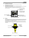
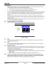
3. The Radio Status LED on the SC3100 should illuminate red (TX) and green (RX) to indicate that the
SC3100 Radio Communicator is transmitting and receiving. If the Radio LED
does not illuminate red to
indicate that the system is transmitting after system Power On, a hardware component failure is possible.
When the SC3100 system detects a hardware failure, the System Status LED on the SC3100 will illuminate