


SC3100
SC3100 Circuit Board
SC3100 Operation and Installation Guide
© 2004 Bosch Security Systems Page 11 90026-201D
2.0 Circuit Board
2.1 SC3100 Circuit Board Components
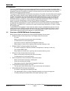
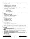
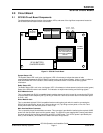
The following describes the function of the headers, LEDs, and some of the significant components located on
the SC3100 Communications Panel circuit board.
MICROPROCESSOR
CHIP, CONTAINS THE
CPU SERIAL NUMBER
AND PID
SYSTEM
STATUS
RADIO
STATUS
MAIN MOLEX
CONNECTOR
JP-1 RESET
JUMPER
“RJ31X” EIGHT
CONDUCTOR
MODULAR JACK
“DIALER” EIGHT
CONDUCTOR
MODULAR JACK
JP-2 RADIO
INTERFACE
SP100 BATTERY
CHARGER BOARD
Figure 2: SC3100 Circuit Board
System Status LED
The System Status LED is a bi-color (red & green) LED. It illuminates to indicate the status of radio
communications between the SC3100 Radio Communicator and the Central Station. It also is used to indicate a
LOW INTERNAL BATTERY condition, and/or identify a hardware failure on the SC3100 during system
initialization.
Radio Status LED
The Radio Status LED is a bi-color (red & green) LED. It illuminates to indicate transmit (red) and receive (green)
Status of the SC3100 internal radio module. This indication is helpful when sending and receiving signals.
RJ31X Modular Jack
This is a standard 8 pin RJ31X compatible female modular phone jack which is used for connecting the SC3100
to the premises RJ31X telephone jack (Tip & Ring on PINS 4 & 5 and House Phone return from the alarm panel
on Pins 1 & 8).
Dialer Modular Jack
This is a standard eight-pin RJ31X compatible female modular phone jack which is used for connecting the
SC3100 to the alarm panel “phone line in & house phone out” (Tip & Ring to alarm panel on Pins 4 & 5 and
house phone return from the alarm panel on Pins 1 & 8).
Main Interface Molex Connector
This is a specially keyed, female Molex connector. This connector is provided for interfacing the required 12VDC
power from the host alarm panel auxiliary power supply. The SC3100 comes supplied with a mating male Molex
connector with a flying lead wiring harness for wiring the 12VDC power. The 12 VDC power is provided by the
Red (+) and the Black (-) wire leads on the Molex connector wiring harness.