


SC3100
Pre-Installation Requirements
SC3100 Operation and Installation Guide
90026-201D Page 16 © 2004 Bosch Security Systems
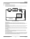
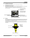
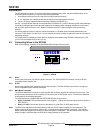
3.5 SC3100 Radio Communicator Location
The SC3100 Radio Communicator is designed to be installed inside of the host alarm panel. If the size of the
host alarm panel will not permit mounting the SC3100 inside or for special SC3100 configurations, then the
SC3100 enclosure can be mounted directly to a vertical surface, like a wall, using the keyhole mounting holes
provided on the rear of the SC3100 enclosure. This type of mounting will also require the use of an L bracket to
mount the factory supplied antenna. This L bracket is provided with all SC3100 units sold by Bosch Security
Systems. The L antenna mount bracket is Bosch Security Systems part number #80072-101.
The SC3100 is not environmentally sealed. Do not mount the SC3100 where it can be exposed to
the elements.
If the antenna is mounted directly on the exterior of the host alarm panel enclosure, the alarm panel should be
mounted on the inside of an exterior wall, for optimum radio transmission and reception. However, it should not
be mounted in close proximity to:
• A cable bundle and/or wiring harness that is routed vertically and in close proximity to the SAFECOM
antenna.
• A computer, PA, entertainment, or sound system.
The following should be considered when determining the location for mounting the SC3100:
• Space restrictions of the host alarm panel.
• Distance to the antenna from the SC3100 Radio Communicator.
• Antenna proximity to a cable bundle and/or wiring harness.
• Antenna proximity to computer, PA, entertainment, or sound systems.
• Easy access by a service technician.
3.6 Antenna Location
Improper antenna location is the single most common problem found in SAFECOM installations. The only way to
properly determine the best location for the SAFECOM antenna installation is to use the SAFECOM IT1500
Tester.
IMPORTANT
The SAFECOM IT1500 Tester must have a minimum of 9dB of attenuation installed between the
Tester and the Tester’s antenna. If the Tester, along with the 9dB attenuator does not produce a
minimum of 10 “pass” indications following the tests, then the SAFECOM SC3100 Radio
Communicator cannot be installed in this location. Refer to the SC9000 Operations Manual section
titled “Using the IT1500 Tester” for more information on finding another location within this
building and testing possible antenna locations. For information on ordering an external
attenuator for your SAFECOM IT1500 Tester, contact a SAFECOM Applications Engineer at (800)
538-5807.
If the SC3100 Radio Communicator is installed inside of a host alarm panel, then the antenna must be mounted
externally to the host alarm panel. Do not mount the antenna inside of the host alarm panel enclosure.
A successful RF communications link between the SC3100 and the Central Station SC9000 computer may be
subject to external interference. Several environmental effects must be considered when determining the proper
location for mounting the SC3100 antenna.
Transmission and receipt of radio signals may be blocked by metal, mountains, hills, foliage and other natural
and man-made obstructions.
Some extent of radio signal degradation may be seasonal. Weather may significantly degrade reception ranges
due to propagation from temperature layers and reflection from the moisture content in the atmosphere.
Transmission and reception ranges may be reduced by dense foliage on trees and shrubs, or by snow. This
degradation is normally experienced during the spring and summer months when the presence of leaves tends
to block the signal path.
For optimum transmission and reception of radio signals, position the antenna as high as is possible within the
structure. Mounting the antenna on an elevated structure will enhance the line-of-sight Tx/Rx range and
communications link effectiveness. The antenna should NOT normally be mounted inside metal buildings or
enclosures. The proper antenna location is site specific for each installation.