


SC3100
Installation
SC3100 Operation and Installation Guide
90026-201D Page 20 © 2004 Bosch Security Systems
The RF bulkhead connector, on the end of the factory supplied coaxial cable, may be installed directly on the
host alarm panel enclosure by using one of the following methods:
1. An existing knock-out port (on the top of the host alarm panel enclosure).
2. A ½ in. diameter hole, carefully drilled into the top of the host alarm panel enclosure.
3. The 2" x 2" factory supplied antenna mounting L-Bracket (P/N 80072-101).
Use the 1.5 inch diameter antenna mounting washers (P/N 80074-101), with the antenna coaxial cable assembly
to provide an adequate ground and physical support for the antenna when mounting the antenna on the top of
the host alarm panel enclosure. The L-bracket installation does NOT require using the antenna mounting
washers.
If a remote antenna location is required, mount the antenna in a suitable location as best determined by the
results of IT1500 Tester. Use the 2-inch x 2-inch antenna mounting L-bracket to attach the antenna to a beam or
supporting structure.
For remote antenna installations, Bosch Security Systems recommends using RG-58 for distances up to 15 ft.
(4.2 m). RG-8 for distances up to 30 ft. (9.1 m).
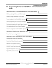
4.3 Connecting Wires to the SC3100
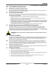
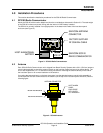
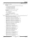
Refer to the following illustration of the SAFECOM SC3100 Radio Communicator:
SAFECOM
1 2 3 4
RJ31-X
DIALER
SYSTEM RADIO
Figure 5: SC3100
4.3.1 Dialer
Connect the alarm panel Tip and Ring to this connector. The SC3100 DIALER connector is an 8 pin RJ31X
compatible female modular jack.
4.3.2 R131X
Connect the premises RJ31X telephone jack to this connector. The SC3100 RJ31X connector is an eight-pin
RJ31X compatible female modular phone jack.
4.3.3 Main Molex Connector
The SC3100 Main Molex connector is to be installed with the factory supplied 6 conductor wiring harness. This
wiring harness contains the wires necessary for connecting the 12 VDC power source. The wires are identified
as described in the following paragraph.
The following wires are supplied with the SAFECOM SC3100 wiring harness:
• Black (-) Ground: Connect the black wire to the negative (-) side of the Host alarm panel auxiliary power 12
VDC SUPPLY.
• Red (+) 12 VDC: Connect the red wire to the positive (+) side of the 12 VDC power source.
Note: The SC3100 is shipped from the factory with the internal 12V DC battery installed, but not connected. The
battery might not be at full capacity after an idle, no-charge period during storage or shipping. The SC3100
Battery should be charged for a minimum of three hours prior to installation. This will ensure that the SC3100
battery charge is sufficient when the SC3100 is initially powered up for operation.