


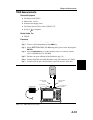
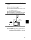

Step 5. Disconnect the Tx (Transmit) coax from System 1 and connect it to the RF Out
port of the Site Master.
Step 6. Disconnect the Rx (Receive) coax from System 2 and connect it to the RF In
port of the Site Master.
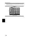
Step 7. Adjust the scale, either manually or by using the AUTO SCALE key, to display
the isolation level in the center of the display.
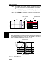
Step 8. Press the
MARKER key and set markers M1 and M2 to identify the receive band
of the amplifier.
Step 9. Press the
LIMIT key and set the limit line to the estimated average signal level.
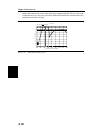
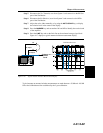
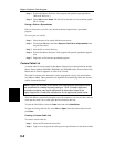
Figure 4-17 displays a typical antenna isolation measurement display.
Typical antenna-to antenna isolation measurements are made between –50 dB and –100 dB
below the 0 dB reference line established by the 2-port calibration.
4-21/4-22
Chapter 4 Measurements
Site Master S251C
Tx
Rx
RF Input
RF Output
Antenna
Isolation
Level
Site Master S251C
Gain/Insertion Loss
Rx
Figure 4-17. Typical Antenna Isolation Measurement Display