


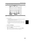
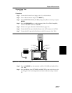

TMA Measurements
Required Equipment
q
Site Master Model S251C
q
Option 10A, Bias Tee
q
External Power Supply 40-115
q
Test Port Extension Cable, Anritsu 15NNF50-1.5C
q
N (m) to
7
16
(m) Adapters
Device Under Test
q
TMA-S
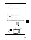
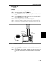
Procedure
Step 1. Connect the External Power Supply (40-115) to the Site Master.
Step 2. Turn on the Site Master and press the
MODE key.
Step 3.
Select INSERTION GAIN (–30 dBm) using the Up/Down arrow key and press
ENTER.
Step 4. Press the
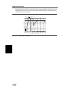
FREQ/DIST key to set the frequency limits. For a TMA-S amplifier,
set F1 to 800 MHz and F2 to 925 MHz.
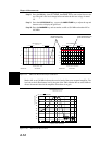
Step 5. Perform a two-port calibration of the Site Master (page 3-4).
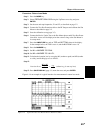
Step 6. Connect the RF Out port of the Site Master to the ANT connector of the TMA.
Step 7. Connect the RF In port of the Site Master to the RX connector of the TMA.
Chapter 4 Measurements
4-13
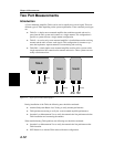
TMA-S
RX ANT
HOLD
RUN
START
CAL
AUTO
SCALE
SAVE
SETUP
RECALL
SETUP
LIMIT
MARKER
SAVE
DISPLAY
RECALL
DISPLAY
PRINT
MODE
FREQ/DIST
AMPLITUDE
SWEEP
SYS
ENTER
CLEAR
ESCAPE
ON
OFF
/
1
2
4
5
6
7
8
9
0
3
+
-
.
Site Master S251C
RF OUTTEST PORT
(BIASTEE)
RF IN TEST PORT
EXTERNAL POWER
SUPPLY (40-115)
TEST PORT CABLE
(OPTIONAL)
TEST PORT CABLE
(OPTIONAL)
Figure 4-8. TMA-S Measurement Setup