


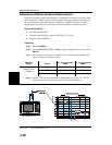

Step 8.
Press the
SYS key, then OPTIONS, then BIAS TEE to turn on the bias tee volt
-
age. The gain is the level change before and after the bias tee voltage is turned
on.
Step 9. Press the
AUTO SCALE key, or press the AMPLITUDE key to adjust the top and
bottom scale, to display the gain level.
Step 10. Press the
MARKER key and set marker set M1 to 834 MHz and marker M2 to
883 MHz.
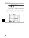
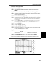
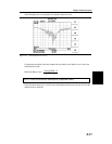
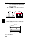
Marker M1 set at 834 MHz indicates the receive band of the tower mounted amplifier. The
level above the 0 dB reference level is the gain of the TMA. Marker M2 set at 883 MHz in-
dicates the transmit band of the amplifier where there is no gain.
Chapter 4 Measurements
4-14
-10
-5
0
5
10
15
800 810 820 830 840 850 860 870 880 890 900
Limit :0.00
M1 M2
Gain/Insertion Loss
2-PORT CAL
Date: 06/13/2001 Time: 15:52:43
Resolution: 130 CAL: ON(COAX)
dB
Frequency (800.0 - 906.0
M1: .01dB @833.68 MHz M2: .00dB @882.99 MHz
-70
-60
-50
-40
-30
-20
-10
0
10
20
800 810 820 830 840 850 860 870 880 890 900
Limit:0.00
M1 M2
Gain/Insertion Loss
TMA
Date: 06/13/2001 Time: 15:38:07
Resolution: 130 CAL:ON(COAX)
dB
Frequency (800.0 - 906.0 MHz)
M1: 12.90 dB @ 833.68 MHz M2: -.92 dB @ 882.99 MHz
REFERENCE LEVEL
AFTER CALIBRATION
GAIN MEASURED WITH
BIAS TEEACTIVATED
Figure 4-9. TMA Gain Measurement After Calibration
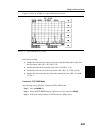
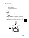
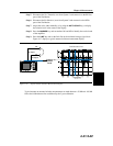
Gain/Insertion Loss
TMA-S CELLULAR
M1: 13.57 dB @ 836.82 MHz
Frequency (750.0 - 925.0 MHz)
Transmission (dB)
20
-20
-30
-40
-50
-60
-70
10
-10
0
750 775 800
825
850 875 900 925
M1
Figure 4-10. TMA-S Gain Measurement