


Insertion Loss Measurement
The transmission feed line insertion loss test verifies the signal attenuation level of the ca
-
ble system in reference to the specification. This test can be conducted with the Site Master
in either FREQ–CABLE LOSS or FREQ–RETURN LOSS mode. In Cable Loss mode, the
Site Master automatically considers the signal traveling in both directions when calculating
the insertion loss, making the measurement easier for the user in the field. Both methods are
explained below.
Required Equipment
q
Site Master Model S251C
q
Precision Open/Short, Anritsu 22N50 or
Precision Open/Short/Load, Anritsu OSLN50LF
q
Precision Load, Anritsu SM/PL
q
Test Port Extension Cable, Anritsu 15NNF50-1.5C
q
Optional 510-90 Adapter, DC to 7.5 GHz, 50 ohm, 7/16(F)-N(M)
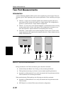
Device Under Test
q
Transmission Feed Line with Short
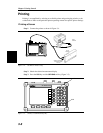
Procedure - Cable Loss Mode
Step 1. Press the
MODE key.
Step 2.
Select FREQ-CABLE LOSS using the Up/Down arrow key and press
ENTER.
Step 3. Set the start and stop frequencies, F1 and F2, as described on page 3-2.
Step 4. Connect the Test Port Extension cable to the RF Out port and calibrate the Site
Master as described on page 3-2.
Step 5. Save the calibration set up (page 3-5).
Step 6. Connect the Device Under Test to the Site Master phase stable Test Port Exten
-
sion cable. A trace will be displayed on the screen as long as the Site Master is
in sweep mode.
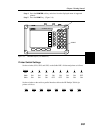
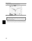
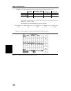
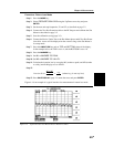
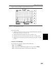
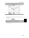
Step 7.
Press the
AMPLITUDE key and set the TOP and BOTTOM values of the dis
-
play. In the example below, the TOP is set to 2, and the BOTTOM is set to 5.
Step 8. Press the MARKER key.
Step 9.
Set M1 to MARKER TO PEAK.
Step 10.
Set M2 to MARKER TO VALLEY.
Step 11. Calculate the measured insertion loss by averaging M1 (marker to peak) and M2
(marker to valley) as follows:
Step 12.
InsertionLoss
MM
=
+12
2
Step 13. Press
SAVE DISPLAY (page 3-5) name the trace, and press ENTER.
Chapter 4 Measurements
4-5