


SWR or Return Loss Measurement
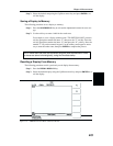
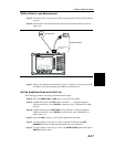
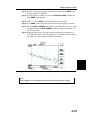
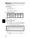
Step 15. Disconnect the Load and connect the test port extension cable to the Site Master
test port.
Step 16. Connect the Load to the open end of the test port extension cable as shown in
Figure 4-9.
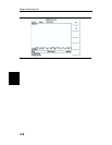
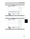
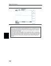
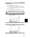
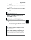
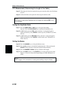
Step 17. Observe the displayed measurement. Figures 4-10 and 4-11 show typical SWR
and Return Loss measurements with markers and limit line set.
Set the Amplitude Scale and Limit Line
The following procedure sets the top and bottom scale display.
Step 18. Press the
AMPLITUDE or LIMIT key to call up the Scale Menu.
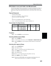
Step 19. In SWR mode, press the
TOP soft key and enter 1, ., 3 using the keypad or
Up/Down arrow key. Press
ENTER to set the top scale. (In Return Loss mode,
enter 0.)
Step 20. In SWR mode, press the
BOTTOM soft key and enter 1 using the keypad or
Up/Down arrow key. Press
ENTER to set the bottom scale. (In Return Loss
mode, enter 5, 4.)
Step 21. Press the
LIMIT soft key to activate the segment limit line table.
Step 22. Use the Up/Down arrow key to scroll to segment #1 and press the
EDIT
SEGMENT
soft key to change the parameter values for segment #1.
Step 23. Use the Up/Down arrow key to scroll to the
START FREQ parameter and press
ENTER to edit the value.
4-11
Chapter 4 Measurements
LOAD
SHORT
MEASUREMENT
RFOUT/REFLECTION
TEST PORT
OPEN
LOAD
SHORT
CALIBRATION
HOLD
RUN
START
CAL
AUTO
SCALE
SAVE
SETUP
RECALL
SETUP
LIMIT
MARKER
SAVE
DISPLAY
RECALL
DISPLAY
PRINT
MODE
FREQ/DIST
AMPLITUDE
SWEEP
SYS
ENTER
CLEAR
ESCAPE
ON
OFF
/
1
2
4
5
6
7
8
9
0
3
+
-
.
Site Master S251B
625.0
2500.0
1384.45 MHz
2096.66 MHz
Figure 4-9. Cable Measurement Test Setup