


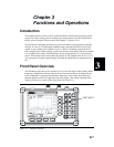
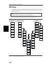

Test Connector Panel
The connectors and indicators located on the test panel are listed and described below.
12.5-15VDC
(1100 mA)
12.5 to 15 Vdc @ 1100 mA input to power the unit or for battery charging.
WARNING
When using the AC-DC Adapter, always use a three-wire power cable connected
to a three-wire power line outlet. If power is supplied without grounding the equip
-
ment in this manner, there is a risk of receiving a severe or fatal electric shock.
Battery
Charging
Illuminates when the battery is being charged. The indicator automatically shuts
off when the battery is fully charged.
External
Power
Illuminates when the Site Master is being powered by the external charging unit.
Serial
Interface
RS232 DB9 interface to a COM port on a personal computer (for use with the
Anritsu Software Tools program) or to a supported printer.
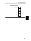
RF Out RF output, 50 W impedance, for reflection measurements.
RF In RF input 50 W impedance for transmission loss or gain measurement.
RF Detector RF detector input for the Power Monitor.
3-2
Chapter 3 Functions and Operations