


Overview
Acquiring A
Satellite
Step 1
Step 2
Step 3
Step 4
Step 5
Step 6
Step 7
71
Operation
After you have completed the assembly of your antenna, you are now ready to become
operational. In order to operate the earth station antenna, you will need to direct it to the
desired satellite adjusting both the elevation and azimuth angles appropriately. The fol-
lowing procedures provide details on how to correctly position your antenna on the
desired satellite.
NOTE: Ensure that the feed system and all electronics are installed properly before pro-
ceeding.
Follow the procedures listed below when acquiring the desired satellite:
Evaluate and determine the required elevation and azimuth angles for the satellite
of interest.
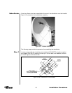
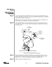
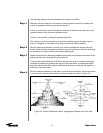
Loosely attach the manual actuator assembly (P/N 207882) to the elevation strut as
shown in Figure 3-22 using the appropriate hardware.
NOTE: The drain hole should be positioned downward for proper water drainage.
Ensure that the locking strut-support setscrew is firmly tightened on the strut assembly
as shown in Figure 3-22.
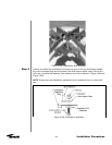
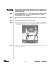
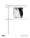
Remove the two indicated strut-support setscrews, and attach the base angle to the cor-
responding strut support using the supplied 1/2 inch clamping nuts and the previously
removed strut-support setscrews as shown in Figure 3-22.
Securely tighten the remaining mounting hardware to achieve the clamping force.
Repeat the entire procedure for the remaining strut assembly.
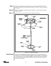
NOTE: DO NOT loosen the Azimuth drive bearings.
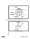
Move the antenna to the desired azimuth angle by adjusting the manual actuator until
the satellite signal has been spotted.
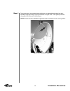
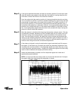
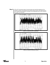
There are several procedures that may be used to properly acquire the satellite. Andrew
recommends that a spectrum analyzer be used. The following procedures provide
explanation as to how to use the spectrum analyzer.
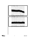
While viewing the spectrum analyzer screen, a pure noise signal as shown in Figure 4-1
will probably be observed. Additionally, some transponder signals may be observed
above the noise signal as shown in Figure 4-2.
Operation