


Manual Actuator
Assembly Removal
Step 1
Step 2
Step 3
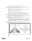
Embedded Pipe
Ground Mount
Elevation
Adjustment
Step 1
Step 2
Azimuth
Adjustment
Step 1
Conclusion
76
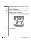
After you have successfully acquired the satellite and all adjustments have been made, the
manual actuator should be removed. The following steps provide the procedure for the prop-
er removal of the manual actuator assembly.
Remove the manual actuator assembly by first removing the hardware securing the actuator
to the base angle.
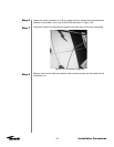
NOTE: The adjustment kit assembly should be removed after the antenna has been adjust-
ed. Store the manual actuator assembly and the corresponding hardware in a dry area for
future use.
Remove the remaining clamp segments with the corresponding hardware.
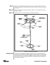
After the antenna is pointed at the satellite, tighten all azimuth and elevation setscrews to 35
foot-pounds.
Loosen the M20 elevation hinge bolts slightly. If coarse adjustment (i.e. more than ± 7.5)
is required then loosen the three square head bolts, and u-bolt to threaded rod, make
adjustment then re-tighten U-bolt. Fine adjustment is performed by working brass nuts
on either side of bracket/U-bolt assembly to push or pull antenna.
Finally, tighten the M20 elevation pivot bolts to 185 N•m. (136 lbs-ft) and check all other
fasteners relating to the elevation strut.
Slightly loosen the eight M16 nuts on the main azimuth hinge u-bolts and square head
bolts and nut, connecting bracket to concrete. Operate the azimuth adjustment strut in
the same manner as the elevation adjuster. When adjustment is complete, tighten the
square head bolts and nut, connecting bracket to concrete and finally tighten the eight
nuts (M16) on the u-bolts to 95 N•m. (70 lbs-ft)
Check that the fasteners on the mount are tightened to the following torque levels:
M16 - 95 N-m (70 lbs-ft)
M20 - 185 N-m (136 lbs-ft)
Operation