


Step 2
Elevation/Azimuth
Strut Assembly
Step 3
39
Installation Procedures
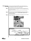
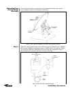
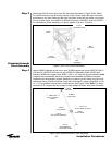
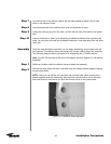
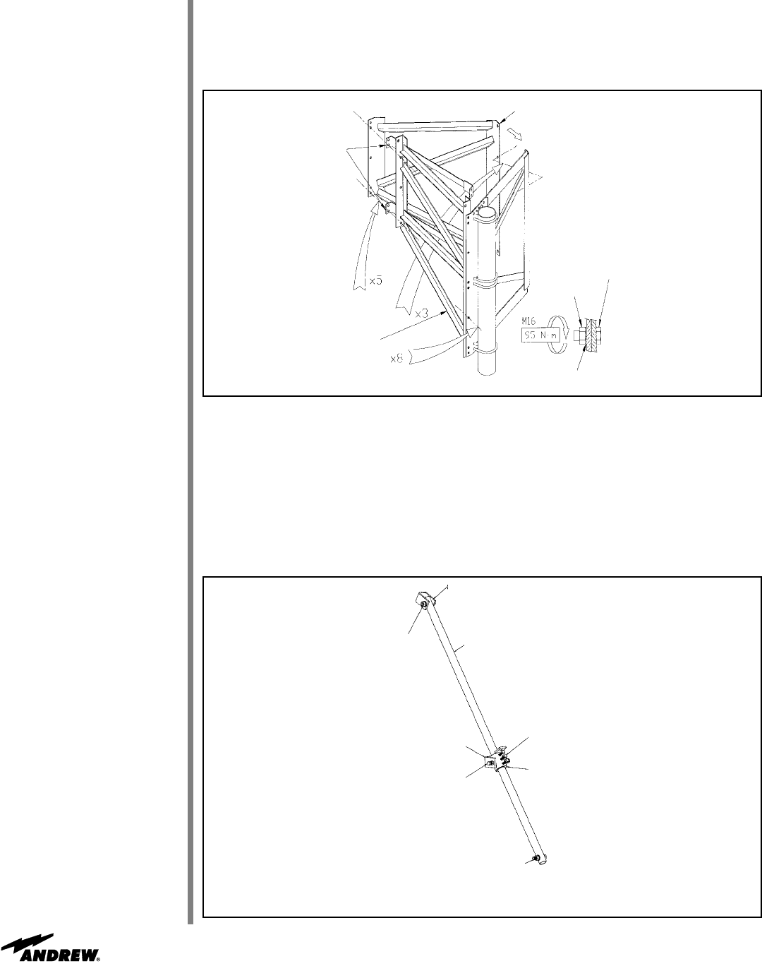
Attach the 104319 front frame to the left side frame as shown in Figure 3-29c. Attach
the 104325 braces to the left side by means of the U-bolts. Attach the right side frame
and braces to the front frame and the right side frame to the left side frame, also shown.
For all of these joints, use 100532-21 M16x40 long bolts, 100526-51 nuts and 100522-
51 lockwashers. When assembly is in place, tighten to 95 N-m. (70 lbs-ft).
Figure 3-29c: Front Frame Attachment
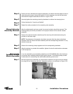
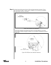
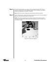
Attach 104638 U-bracket to one end of each 301899 support pipe using 100537-87 M20 X
100 hex bolt, 100526-57 M20 hex nut and 100522-57 lockwasher. Attach 301900 strut
bracket to 49258 strut support using 45980-1 .625-11 x 2" long bolt and nut assembly. Note:
Long bolt and nut assembly should not protrude inside diameter of 49258 strut support.
Assemble strut bracket/strut support assembly to support pipe by sliding over strut with
welded tab facing 104638 U-bracket. Snug the strut support in place using 9953-15 .50-
13 x 1.5" long square head screws in three places. See Figure 3-29d. Note: For eleva-
tions above 75° reverse the strut support so the welded tab faces away from U-bracket.
Figure 3-29d: Elevation/Azimuth Strut Assembly
104321
Right Side Frame
104325
Brace
104319
Front Frame
M16
Nut
M16
Hex Bolt
M16
Lockwasher
M20 x 100
Bolt, Lockwasher
and Nut
104638
U-Bracket
301899-2
Support Pipe
301900
Strut Bracket
5/8 x 2”
Bolt and Nut Assembly
49258
Strut Support
1/2 x 1-1/2”
Square Head Set Screw
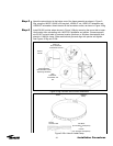
3/4 x 3”
Bolt, Flatwasher,
Lockwasher and Nut